N Connector

The N connector is a type of coaxial connector that is widely used in the field of radio frequency (RF) technology. Also, known as Type-N connector or N type connector. It is a threaded connector that provides a secure and reliable connection for RF applications. The N connector has been around since the 1940s and has undergone several improvements and modifications over the years. The N connectors also are known as Type-N Connector. The N male connector is typically used to connect an antenna or other RF device to a coaxial cable.The N female connector is commonly used as a panel-mount connector and is often found on RF equipment such as radios, transmitters, and amplifiers.
The N connector has several advantages over other types of coaxial connectors. It has a low loss, which means that it can transmit RF signals with minimal attenuation. It also has a high power handling capability, which makes it ideal for high-power applications. Additionally, the N connector is weather-resistant and can withstand exposure to the elements, making it ideal for outdoor use.
The type N connector is an essential component in the field of RF technology. It is a reliable and secure connector that is used in a wide range of applications, from connecting antennas to coaxial cables to panel-mounting RF equipment.There are several types of N connectors, including the N male connector, N female connector, N type bulkhead connector, and N connector antenna. Each type of N connector has its own unique features and applications, and it is important to choose the right connector for your specific needs. Whether you are building a Wi-Fi network or designing a cellular base station, the N connector is a versatile and essential component that can help you achieve your goals.
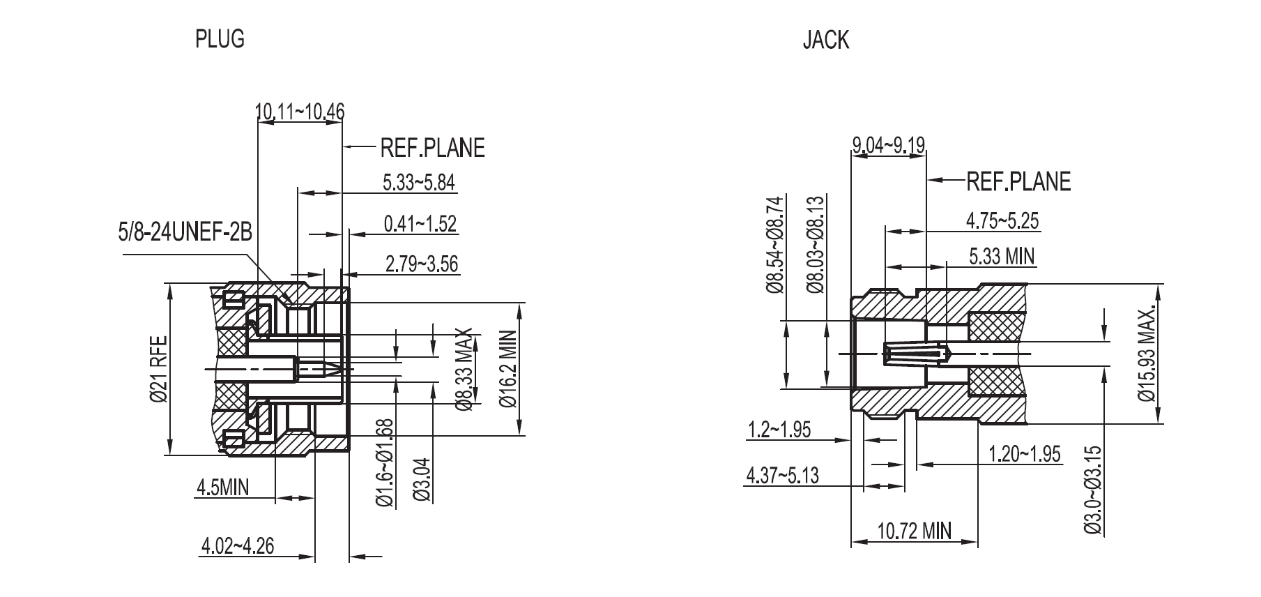
Interface Of N Connector
![interface drawing of N connector]()
Specification Of N-Type Connector
| Electrical |
|
| Impedance | 50 Ohm |
| Frequency Range | DC - 11 GHz |
| Return loss | ≥ 26 dB Typical |
| Insertion loss | ≤0.1 dB x √f GHz |
| Voltage Rating | 500 Volts RMS Continuous |
| Dielectric Withstanding Voltage | 1500 VRMS Max |
| Insulation Resistance | ≥ 5000 MΩ Min |
| Center Contact Resistance | ≤1 mΩ Max |
| Outer Contact Resistance | ≤4 mΩ Max |
| RF Leakage | -90 dB Max (DC-3GHz) |
| Passive Intermodulation (PIM) | -166 dBc with 2 X 43 dBm inputs |
| Power Handling | 300 W @ 10 GHz @ 25ºC |
| Environmental |
|
| Temperature Range | −65°C to +165°C |
| Thermal Shock | MIL-STD-202, Method 107 (Test Condition B) |
| Corrosion | MIL-STD-202, Method 101 (Test Condition B) |
| Vibration | MIL-STD-202, Method 204 (Test Condition B) |
| Mechanical Shock | MIL-STD-202, Method 213 (Test Condition I) |
| Moisture Resistance | MIL-STD-202, Method 106 |
| Altitude | MIL-STD-202 Method 105 (Test Condition C) |
| Mechanical |
|
| Mating Cycles | 500 Min |
| Coupling Mechanism | Threaded |
| Interface Specification | MIL-STD-348, IEC 61169-16, MIL-PRF-39012, CECC 22210 |
| Mating Torque | 0.7 Nm to 1.1 Nm |