1. Introduction
This article analyzes the failure modes and mechanisms of RF coaxial connectors and cable assemblies and discusses in detail how to improve their reliability.
Currently, there are many types of RF coaxial connectors used in the market. However, they can be categorized into three main types based on connection mechanisms:
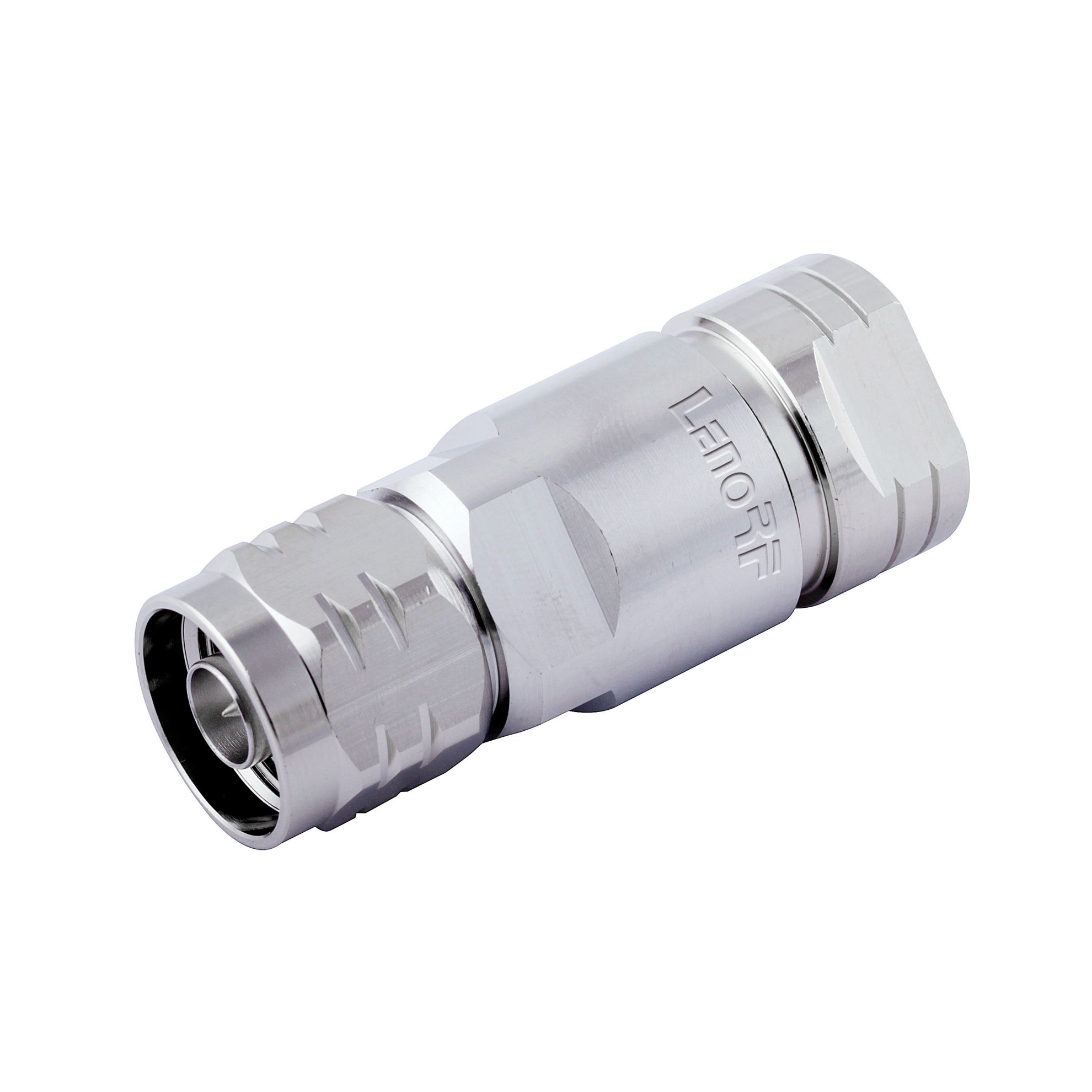
![87-5161-244-01 N MALE CLAMPING 1-2R 87-5161-244-01 N MALE CLAMPING 1-2R]()
Threaded Connectors : APC-7, N, TNC, SMA, SMC, 1.6/5.6.
These connectors offer high reliability and excellent shielding, making them the most widely used.
![70-6-0010,N-BNC-KJ-1 70-6-0010,N-BNC-KJ-1]()
Bayonet Connectors : BNC, C, SHV, MHV.
Known for their quick and convenient connection mechanism, these were among the earliest RF connectors used internationally.
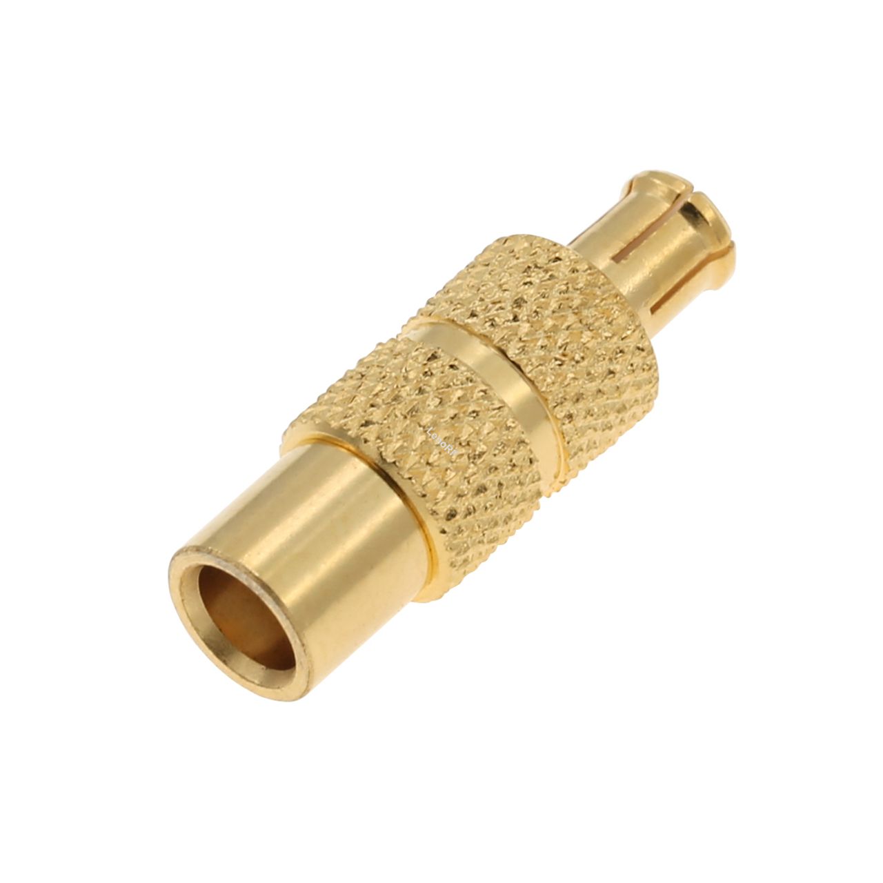
![80-18-001,MCX-JK-1 80-18-001,MCX-JK-1]()
Push-in Connectors : SMB, SSMB, MCX, MMCX, 1.0/2.3.
These connectors feature simple and compact designs, making them ideal for miniaturized applications.
Despite the variety of connector types, many reliability issues are similar. This article focuses on analyzing the failure modes and mechanisms of the most widely used type: threaded RF coaxial connectors. Based on over a decade of experience, the most common failure modes include the following.
2. Failure Modes
2.1 Connection Failures
a. Connector Nut Detachment
Some users report that connector nuts occasionally fall off, especially in small connectors like SMA, SMC, and SSMA. The main reasons include:
Material selection errors – Brass, which lacks elasticity, is mistakenly used for retaining rings to reduce costs, making nuts prone to detachment.
Insufficient groove depth – The groove for the retaining ring is not deep enough, causing the nut to fall off under minimal torque.
Unstable processing quality – Beryllium copper's elastic treatment does not reach the required hardness, making the retaining ring ineffective.
Improper tightening – Using standard wrenches instead of torque wrenches results in excessive torque, damaging the retaining ring and causing the nut to fall off.
b. Loose or Detached Inner Conductor
Lack of barbs or reverse threads in the design makes the inner conductor prone to displacement.
Incorrect barb processing dimensions result in inadequate retention force.
2.2 Reflection Failures
a. Increased Reflection
Every connector has a defined lifespan. For instance, SMA connectors are rated for 500 mating cycles per international standards. Exceeding this limit causes wear and degradation, leading to significant reflection increases. Many users continue using worn-out connectors, which compromises measurement accuracy and data reliability.
b. Open Circuit
Users sometimes mistakenly connect an N-type 50-ohm plug to an N-type 75-ohm socket. Since the 50-ohm conductor is larger than the 75-ohm socket hole, it deforms the socket beyond its elastic limit, causing permanent damage and an open circuit when another user attempts to connect later.
c. Short Circuit
During testing of sealed connectors, some were found to have high VSWR or total reflection due to solder flow onto the glass insulator surface, causing partial or complete short circuits.
2.3 Electrical Contact Failures
a. Lack of Contact Between Pin and Socket
Some manufacturers use H59-1 brass instead of beryllium or phosphor bronze to reduce costs. After a few mating cycles, the socket loses its elasticity, preventing proper contact.
Even when using beryllium copper, improper quality control may allow non-conforming parts (e.g., those with improper slot closure) to be mixed in, leading to non-contact issues.
b. Poor Contact
Elastic component degradation – Improper aging treatment leads to decreased elasticity and lower contact pressure after multiple mating cycles.
Dimensional non-conformance – Variations in pin diameter or socket closure lead to loose fitting and intermittent electrical contact.
Excessive wear – Over time, excessive mating cycles cause severe wear and loss of elasticity.
c. Corrosion
Inadequate pre-treatment before plating leaves behind oil or oxidation, reducing plating adhesion.
To lower costs, manufacturers may use thinner plating, accelerating corrosion and reducing lifespan.
2.4 Cable Assembly Failures
Cable assemblies consist of RF connectors and coaxial cables, meaning they inherit the failure modes of connectors. Additionally, failures may occur at the connector-to-cable junction. Common cable assembly types and their associated failure mechanisms include:
a. Threaded Clamp Type
Loose nut under vibration – Leads to increased contact resistance and insertion loss.
Over-tightening – Damages shielding braid, reducing tensile strength.
b. Soldered Type
Cold solder joints – Increase contact resistance and insertion loss.
Repeated stress – Deforms shielding braid over time, reducing tensile strength until failure occurs.
c. Crimped Type
Insufficient crimping – Results in poor contact between the crimp tube and shield.
Over-crimping – Reduces tensile strength, making the assembly prone to failure.
3. Conclusion
LenoRF based on over 20 years of experience in RF coaxial connector and cable assembly design and production, this article provides a detailed analysis of common failure modes and mechanisms. It is crucial to recognize that failure modes are often interconnected.
For example, poor pin-socket contact can lead to open circuits, increased contact resistance, insertion loss, and reflection failures, ultimately affecting the entire system. Addressing these issues comprehensively is essential to improving the reliability of RF coaxial connectors and cable assemblies.


