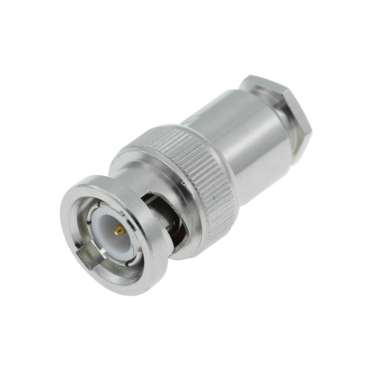
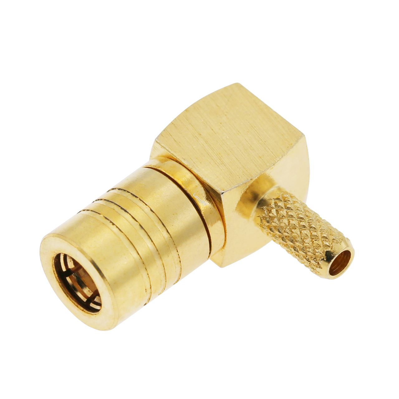
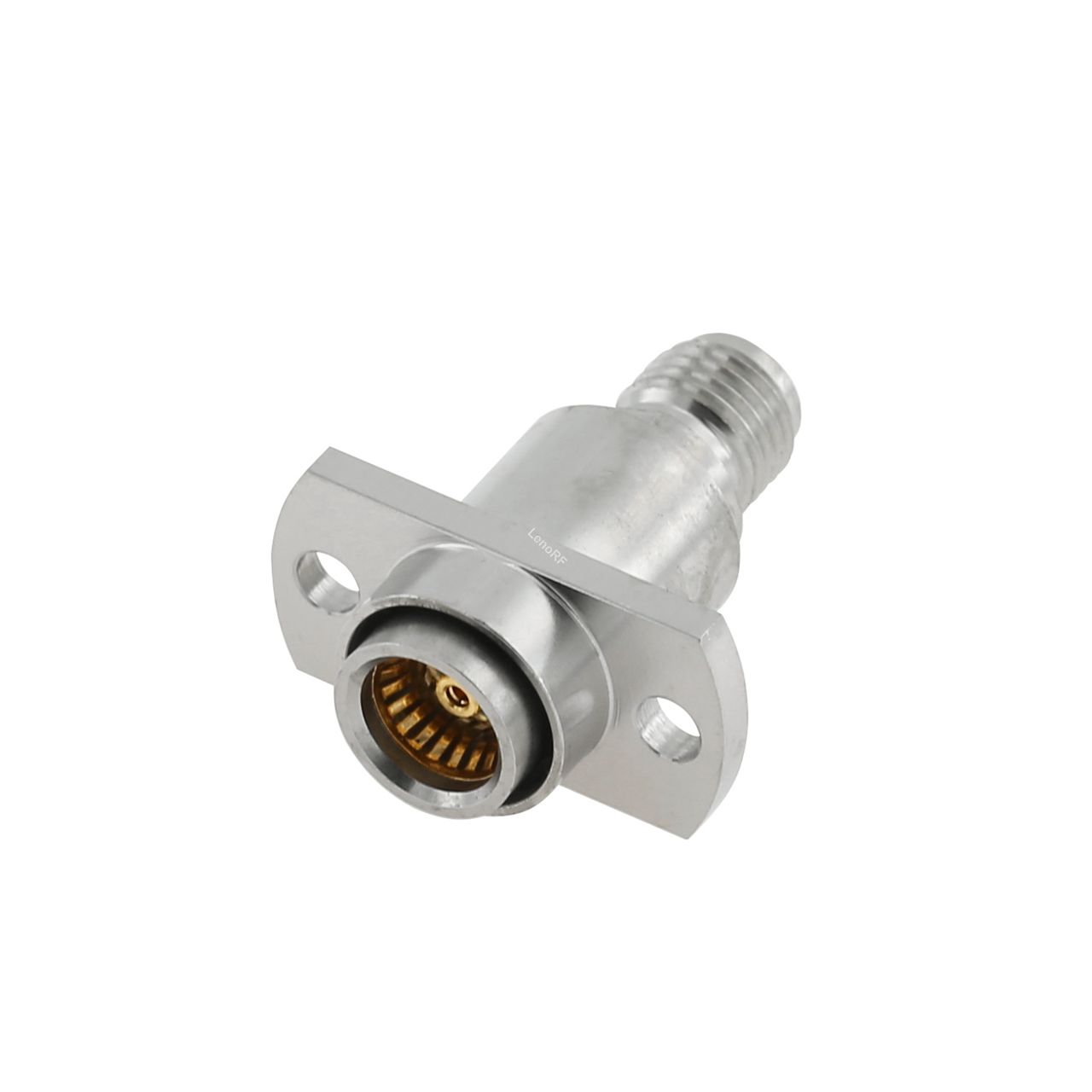
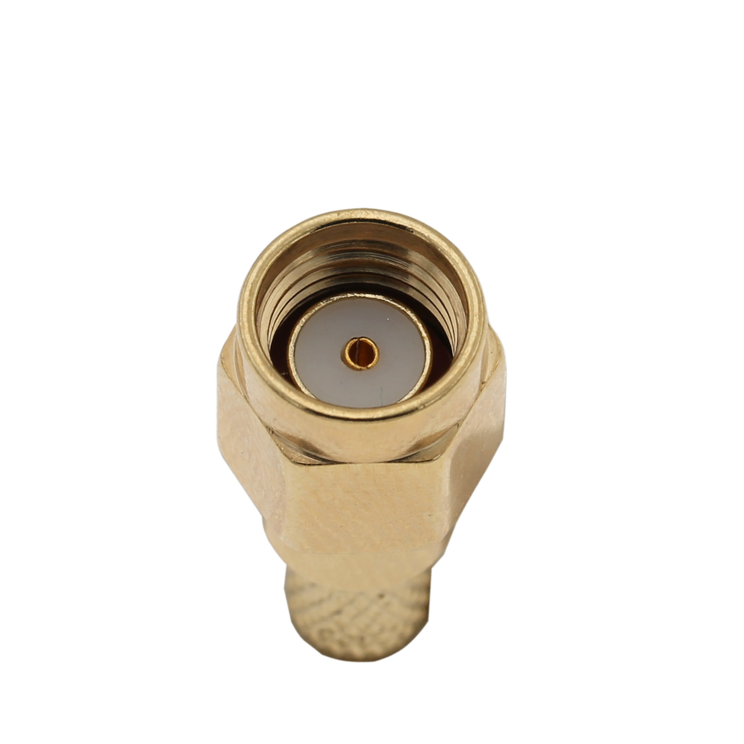
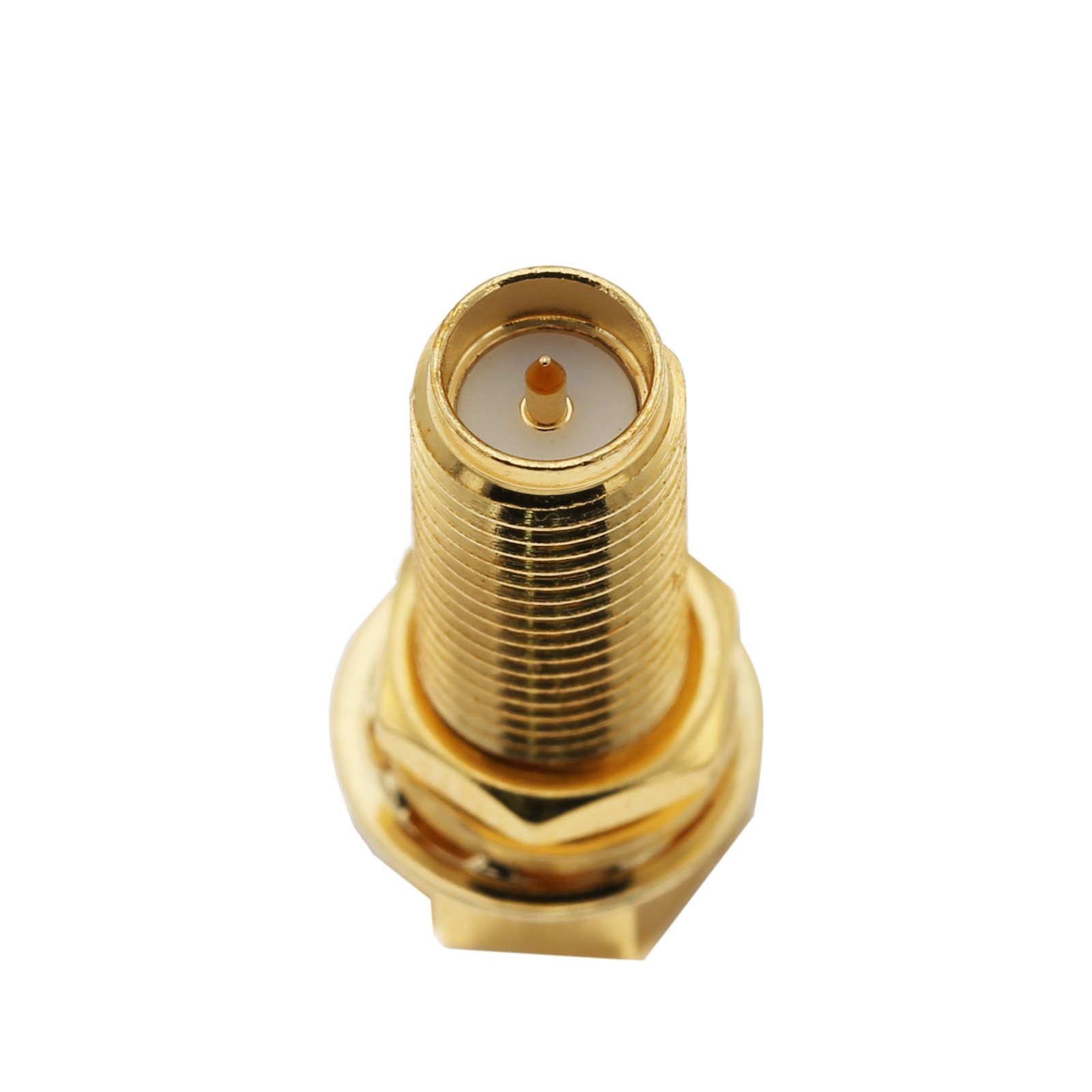
![N plug lock connector N plug lock connector]()
Section One:Basic Information about RF Connectors
RF connectors (Radio Frequency Connectors) are electrical connectors used for transmitting RF signals. In the industry, they are also known as coaxial connectors because they are usually connected to coaxial cables and have a coaxial structure.
![Coaxial Structure]()
Overview
RF connectors are passive electronic components that achieve corresponding electrical performance through precision parts and assembly accuracy. Industry insiders often refer to them humorously as small hardware screws. In reality, products from different factories can vary significantly, which greatly relates to the understanding and management level of the product. Although RF connectors are a highly segmented category within the connector industry, they have developed many models over decades. As critical components in communication systems, they must meet multiple electrical performance parameters and different usage environments, with many structural changes depending on the application scenario. With over 20 years of experience in the field, I hope this guide can help readers better understand and choose the right RF connectors.
Terminology
Radio Frequency (RF): RF waves typically cover the frequency range from several kilohertz (kHz) to 300 GHz. This includes AM and FM broadcasting, radio communications, WLAN (Wi-Fi), Bluetooth, and microwave bands.
Microwave: Microwave bands typically refer to the frequency range from 1 GHz to 300 GHz. Microwaves are commonly used in radar, satellite communications, microwave ovens, and high-frequency applications like radio beam transmission.
Connector Grades
Before selecting a connector, it is essential to understand the required grade of the RF connector. Different grades of connectors have significant differences in performance and price:
Standard Test Connectors (Grade 0)
High-Performance Connectors (Grade 1)
General Purpose Connectors (Grade 2)
Grade Definitions
General Purpose Connector (Grade 2): Manufactured with the widest allowable dimensional tolerances but still ensuring minimal specified performance and interoperability. Reflectance requirements may or may not be specified.
High-Performance Connector (Grade 1): Specifies reflectance limits according to frequency variations. The dimensional tolerances required for Grade 1 connectors are not necessarily stricter than those for Grade 2, but manufacturers must choose tighter tolerances to meet reflectance requirements.
Standard Test Connector (Grade 0): A precision-manufactured specific type of connector used to measure reflectance of Grade 1 and Grade 2 connectors. Measurement errors caused by these connectors can be ignored.
Laboratories and instruments typically use Grade 0 connectors. Telecom, communication, medical, and industrial applications commonly use Grade 1 connectors, while consumer electronics usually use Grade 2 connectors. Military connectors have specific requirements under national military standards.
Section Two:
Materials and Plating of RF Connectors
The materials and plating of RF connectors play a crucial role in their performance, reliability, and durability. Choosing the right materials and plating processes is key to ensuring excellent performance and reliability of RF connectors in various applications.
Common Material Types
Parameter | Pure Copper | Beryllium Copper | Phosphor Bronze | Brass | Stainless Steel | Aluminum |
Contact Resistance | ++ | + | + | + | – | + |
Abrasive Resistance | – | 0 | 0 | – | + | – |
Discoloration | – | 0 | 0 | + | + | + |
Price | + | –– | + | ++ | – | – |
Note: Grade Definitions: ++ (Excellent/Very Low Price), + (Good/Low Price), 0 (Average), – (Low), –– (Very Low/Very High Price). Contact resistance should be as low as possible. ++ (Excellent/Very Low Price).
Common Plating Types
Parameter | Gold | Silver | Pure Copper | Nickel | Ternary Alloy | Chemical Nickel-Plated Gold |
Contact Resistance | ++ | ++ | ++ | + | ++ | ++ |
Third-Order Intermodulation | ++ | ++ | N/A | 0 | ++ | ++ |
Magnetic Residual | ++ | ++ | ++ | –– | ++ | ++ |
Abrasive Resistance | + | 0 | – | + | + | + |
Adhesion | ++ | + | ++ | + | ++ | ++ |
Discoloration | ++ | –– | – | –– | + | ++ |
Price | –– | – | + | 0 | + | 0 |
Note: Grade Definitions: ++ (Excellent/Very Low Price), + (Good/Low Price), 0 (Average), – (Low), –– (Very Low/Very High Price). Contact resistance should be as low as possible. ++ (Excellent/Very Low Price).
Section Three:
Electrical Performance of RF Connectors
Electrical Performance | Ideal Value | Actual Value | Causes and Tips |
Impedance (Ω) | Z0 ± 0 (e.g., 50 or 75 ohms) | Z0 ± X | Due to dimensional steps and other discontinuities, it is impossible to maintain uniformity of Z0. |
Frequency (Hz) | Maximum value achieving TEM mode | Limited by the interface standard of the connector | Depends on signal attenuation, VSWR, and mode changes. |
VSWR (Voltage Standing Wave Ratio) | 1.0 (no reflection) | > 1.0 | Impedance discontinuities in the transmission line will cause the VSWR to increase. |
RF Leakage | No leakage | >120 dB (frequency-related) | Depends on the shielding efficiency of the cable’s outer shield and working frequency. |
Insertion Loss (dB) | 0 dB (no loss) | ≤0.5 dB | The insertion loss of the connector can be negligible depending on the cable. |
Dielectric Withstanding Voltage | Higher than the breakdown voltage of the cable | Usually smaller | Depends on the dielectric strength of the material and the electrical gap between the inner and outer conductors. |
Working Voltage | Higher than the breakdown voltage of the cable | Usually smaller | Depends on the proportion of the inner and outer conductors and the dielectric. |
Insulation Resistance (Ω) | ∞ (infinite) | < ∞ | Dielectric attenuation depends on the material and size of the insulator. |
Contact Resistance (mΩ) | 0 (no contact resistance) | >0 | Depends on the terminal’s positive pressure, material properties, and plating type. |
Common Characteristic Impedance Values
RF systems typically use 50-ohm or 75-ohm impedance.
50 ohms: Common in most RF applications such as wireless communications, radar, and microwaves.
75 ohms: Common in video and broadcast applications.
Matching impedance: Ensure the connector impedance matches the cable and system impedance to minimize reflection and signal loss. Different impedance connectors cannot be interconnected as it may damage the connectors and cause severe echo loss due to impedance mismatch.
Frequency
Different connectors are suitable for different frequency ranges. For example:
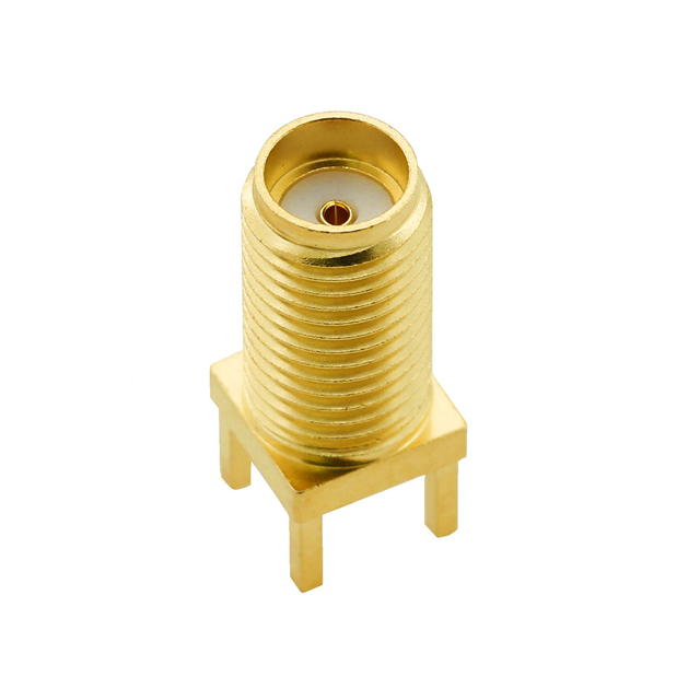
![PCB.114SMAFSTJ.A-3 PCB.114SMAFSTJ.A-3]()
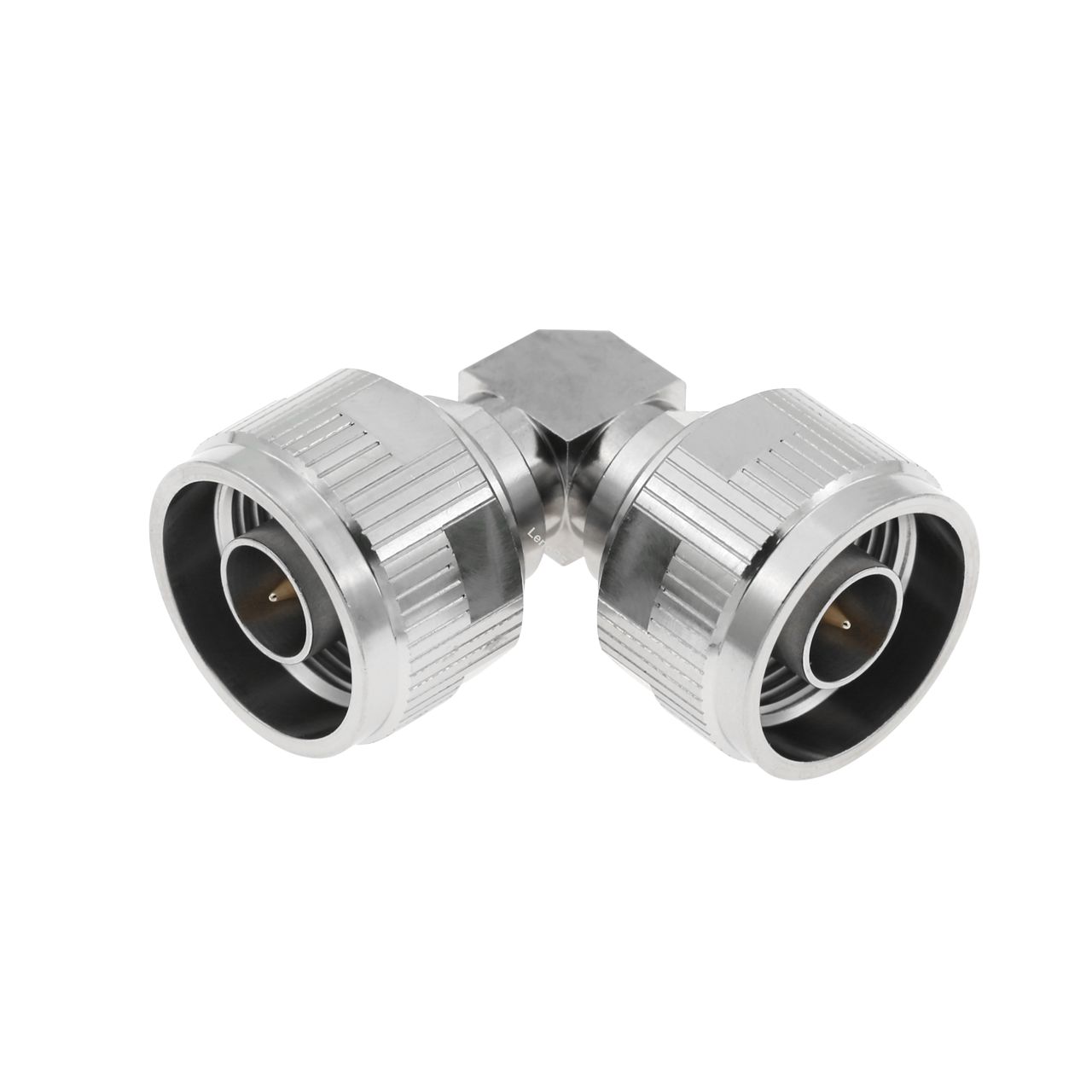
![80-11-002,N-JJWG 80-11-002,N-JJWG]()
![82-7161-104-02 _82-7161-104-01 BNC PLUG CRIMP FOR RG179 CABLE 82-7161-104-02 _82-7161-104-01 BNC PLUG CRIMP FOR RG179 CABLE]()
Determine the frequency range required by your application and choose connectors that can operate within these frequencies. For example, if a microwave system operates at 38 GHz, choosing an SMA connector will result in a significant drop in electrical performance after 26.5 GHz. You should select connectors like the 2.92mm type or higher.
Frequency Range | Wavelength | Name | Abbreviation | IEED Band |
3~30Hz | 100~10KM | Ultra long wave | VLF |
|
30~300Hz | 10~1KM | long wave | LF |
|
300~3000Hz | 1~0.1KM | medium wave | MF |
|
3~30MHz | 100~10M | short wave | HF | HF |
30~300MHz | 10~1M | Ultra short wave | VHF | VHF |
300~3000MHz | 1~0.1M | ultrashort wave | UHF | UHF,L,S |
3~30GHz | 10~1CM | Microwave | SHF | SHF S, C, X, Ku, K, Ka |
30~300GHz | 1~0.1CM | Milliwave | EHF | Ka, V, W, mm |
300 GHz – 3 THz | 1 mm – 0.1 mm | Terahertz waves | THF |
|
![frequency chart]()
Voltage Standing Wave Ratio (VSWR)
VSWR measures the signal reflection degree in an RF transmission line or antenna system. The closer the VSWR is to 1:1, the smaller the reflection and the better the match. At VSWR = 1:1, there is no reflected wave, and the system is perfectly matched, with all input power absorbed by the load. When VSWR > 1:1, part of the signal is reflected, indicating system mismatch. The higher the VSWR, the more severe the reflection, and the lower the efficiency.
Common VSWR Values
Connector Type | Frequency Range (GHz) | Typical VSWR |
SMA | DC to 18 | DC to 6: ≤ 1.15; 6 to 12: ≤ 1.25; 12 to 18: ≤ 1.35 |
BNC | DC to 4 | DC to 1: ≤ 1.2; 1 to 2: ≤ 1.3; 2 to 4: ≤ 1.5 |
N Type | DC to 11 | DC to 4: ≤ 1.2; 4 to 8: ≤ 1.25; 8 to 11: ≤ 1.3 |
TNC | DC to 11 | DC to 4: ≤ 1.2; 4 to 8: ≤ 1.25; 8 to 11: ≤ 1.3 |
7/16 DIN | DC to 7.5 | DC to 3 GHz: ≤1.1, 3 to 7.5 ≤ 1.2 |
MCX | DC to 6 | DC to 3 GHz: ≤1.2, 3 to 7.5 ≤ 1.35 |
MMCX | DC to 6 | DC to 3 GHz: ≤1.2, 3 to 7.5 ≤ 1.35 |
QMA | DC to 6 | DC to 3 GHz: ≤1.15, 3 to 7.5 ≤ 1.25 |
When selecting connectors, ensure their VSWR values match or are better than the system requirements.
RF Leakage
RF leakage refers to the signal leakage from the connector, which can interfere with nearby devices or be affected by external interference. High-quality connectors can minimize RF leakage.
Insertion Loss
Insertion loss measures the signal loss due to the connector. It is the ratio of the input power to the output power of the connector. Low insertion loss indicates high signal transmission efficiency. Ideally, the insertion loss should be close to 0 dB.
Insulation Resistance and Contact Resistance
Insulation resistance should be as high as possible to prevent leakage currents. Contact resistance should be as low as possible to ensure good electrical contact.
PIM Third-Order Intermodulation (Passive Intermodulation)
A common nonlinear distortion phenomenon in RF and microwave systems. It typically occurs in environments where multiple signals coexist, caused by connectors, and negatively impacts system performance and signal quality. Third-order intermodulation products can generate interference within the receiving band, leading to a decrease in signal-to-noise ratio, which in turn affects the performance and reliability of communication systems.
Some typical causes of intermodulation products:
Oxidized metal contact surfaces: Caused by materials like aluminum or other oxidized coatings but can be avoided by using silver.
Ferromagnetic materials: Materials such as steel and stainless steel can cause nonlinear behavior.
Current saturation: Nonlinearities in current and voltage.
High corona levels: Plasma effects.
Small cracks: Occur at contact surfaces and other locations.
Grease layers, etc.: Present between contact parts, causing impure contact.
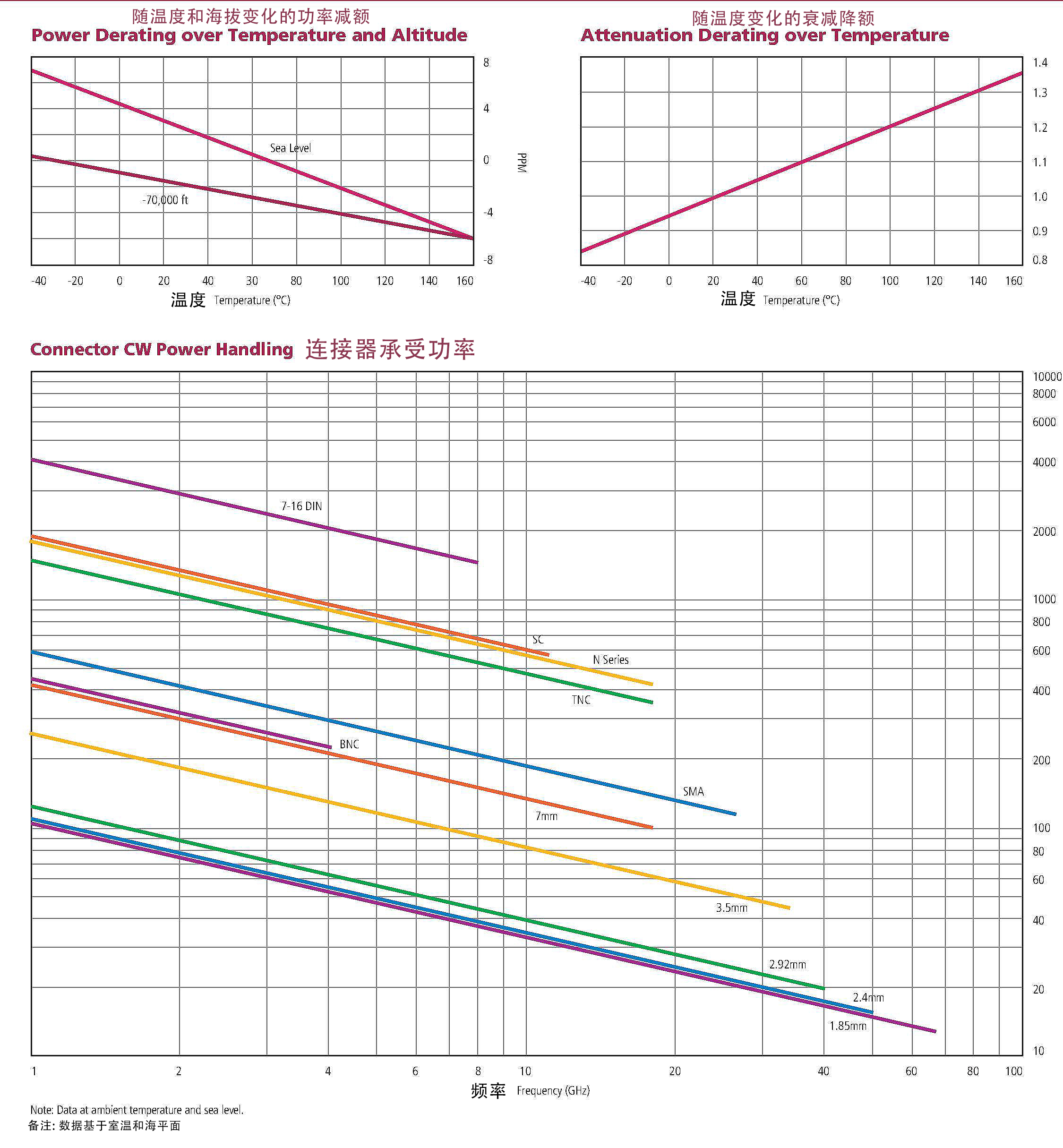
Power Rating:
Different connectors can handle different power levels. Ensure that the connectors can handle the maximum power transmitted by the system without degradation or damage.
The following chart shows the power handling capabilities of common connectors:
![power-handling]()
Section Four:The Classification of RF connector
Classification of Connectors by Size
Type | Series |
Micro | MCX, MMCX, SMP, SMPM, SSMP |
Subminiature | BMA, SMA, SMB, SMC, SMS, QLA, QMA, 1.0/2.3 |
Small | BNC, BNO, BNT, MHV, SHV, TNC |
Medium | N, QN, 4.3/10, 4.1/9.5 |
Large | 7/16, EIA |
Precision | 3.5mm, 2.92mm, 2.4mm, 1.85mm, 1.0mm |
Examples of Common RF Connectors
SMA: High frequency, threaded, commonly used in lab equipment and RF modules.
BNC: Low frequency, bayonet coupling, used in Ethernet, surveillance systems, and video signal transmission.
N-type: Higher power handling capability, reliable threaded connection, used in RF and microwave applications such as communication base stations.
MCX/MMCX: Small size, quick push-on coupling, used in GPS and mobile applications.
2.92mm: Millimeter wave, threaded connection, air dielectric, used in lab testing and millimeter wave applications.
Classification by Coupling Method
![ssma plug ra rg401 ssma plug ra rg401]()
![20-371,bnc plug clamp rg58 20-371,bnc plug clamp rg58]()
![22-002, smb plug ra crimp rg316 22-002, smb plug ra crimp rg316]()
Snap-on (e.g., SMB, MCX, SMP): Quick plug and unplug, relatively low retention force, typically used in PCB.
![QN-JW-38S, QN male right angle for superflexible 38 cable QN-JW-38S, QN male right angle for superflexible 38 cable]()
![SMA-BMA-KKFG-2 SMA-BMA-KKFG-2]()
Push-pull self-latching (e.g., 1.0/2.3, BMA): Quick plug and unplug after unlocking, high retention force.
Classification by Connection and Installation Methods
RF connectors can either connect to a cable or to a PCB or microstrip line, which can be confusing for many users. For instance, connectors named SMA can look very different despite sharing the same designation.
Inner Conductor Connection Methods (inner conductor connecting to the cable's inner conductor or PCB):
Outer Conductor Connection Methods (outer conductor connecting to the cable shield or PCB ground):
Crimping
Clamping
Soldering
Solderless compression
Panel Mounting Methods (how connectors are fixed to panels):
Bulkhead
Two-hole flange
Four-hole flange
Ceramic feedthrough
PCB Mounting Methods (how connectors are fixed to PCBs):
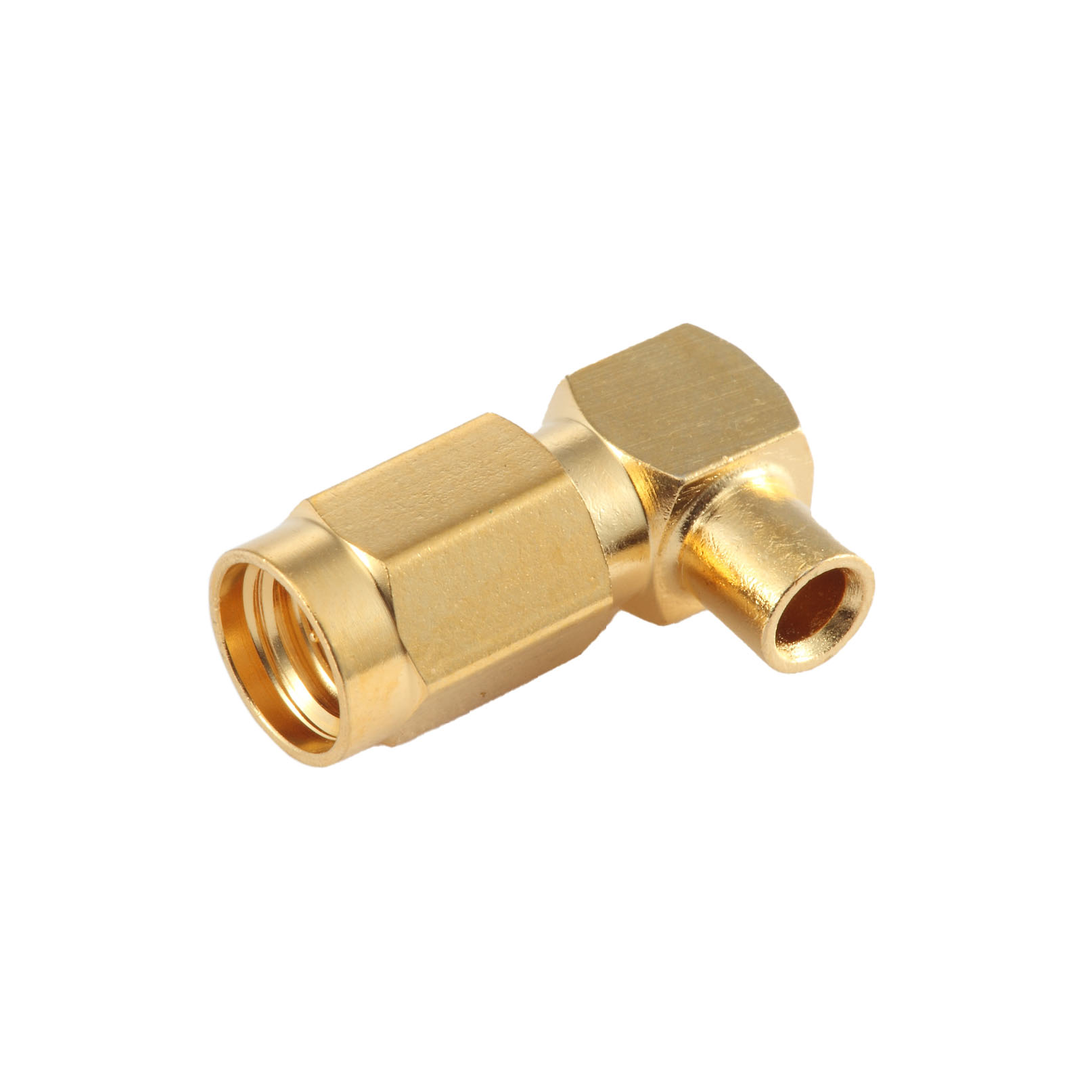
Below are some types of commonly used RF connectors along with their images.
Section Five:Other Considerations
1. Connector Durability
Mating Cycles: Consider the number of times a connector can be mated and unmated without degrading performance. Most connectors typically support 500 or more mating cycles.
2. Polarity
To prevent incorrect connections, engineers design reverse polarity connectors. Normally, a male connector should have a male pin, but in reverse polarity connectors, a male connector has a female socket. As shown in the diagram:
![rp-sma plug]()
![rp-sma jack]()
3. Compatibility
Standards Compliance: Ensure the connectors comply with industry standards (e.g., IEC, MIL-STD) for interoperability and consistent performance. Connectors with different interface sizes (standards) are not interchangeable.
Cable Compatibility: Ensure the connectors match the type and size of cable you are using to achieve optimal performance. It is difficult to achieve good performance when using miniature RF connectors with thicker cables.
4. Cost
5. Environmental Conditions
Waterproof Rating: For outdoor or harsh environments, choose robust connectors with environmental sealing (e.g., IP66, IP67 waterproof connectors).
Salt Spray Requirements:
Temperature Range: Ensure connectors can operate within the expected temperature range of the application. Common connector temperature ranges are -55°C to 165°C. The working temperature mainly relates to the material of the insulator. PTFE's maximum temperature is 165°C, PEEK's continuous use temperature can reach 200°C, with short-term use up to 300°C. PEI's long-term use temperature can reach 180°C, with short-term exposure up to 220°C.
Below is the reflow soldering temperature curve for connectors with brass housings and PTFE insulators.
Summary
When selecting RF connectors, consider the following factors:
Grade: Choose the appropriate grade based on the application (Standard Test, High-Performance, General Purpose).
Material and Plating: Select suitable materials and plating for performance, reliability, and cost.
Electrical Performance: Ensure impedance, frequency, VSWR, RF leakage, insertion loss, dielectric withstanding voltage, working voltage, insulation resistance, and contact resistance meet system requirements.
Mechanical Performance: Consider mating cycles, mating force, durability, and temperature range.
Connector Type: Select the appropriate type (SMA, BNC, N Type, TNC) based on the application's frequency range and impedance requirements.
Conclusion Choosing the right RF connector requires understanding the specific requirements of your application, including frequency, impedance, power, environmental conditions, and connection methods. By considering these factors, you can select connectors that ensure optimal performance and reliability.


