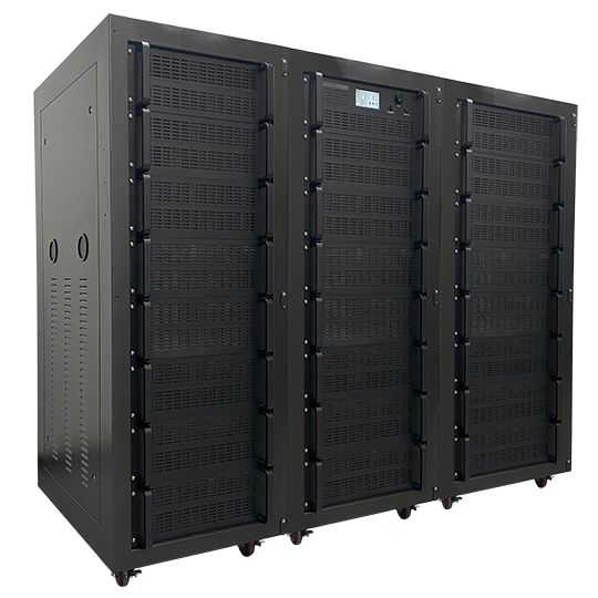
As EMC immunity standards tighten and high-frequency communication protocols expand, test engineers face mounting pressure. You must generate high, continuous field strengths across wider frequency bands without equipment degradation. Relying on narrow-band or legacy amplification systems creates immediate bottlenecks on the test floor. It forces frequent equipment swapping, introduces signal distortion during complex modulation, and risks outright test failure due to poor load mismatch handling. Specifying the correct equipment requires shifting your focus. You have to look past familiar wattage numbers on a datasheet and evaluate the actual RF task at the output port. This guide provides a technical framework for evaluating and selecting a broadband microwave power amplifier. We address stringent EMC, radar, SATCOM, and communication testing requirements directly, giving you the field-tested strategies needed to keep your chambers running without interruption.
Key Takeaways
Start at the Output: Successful microwave amplifier selection begins by defining the required field strength (V/m) at the antenna or transducer, factoring in cable losses and antenna gain, rather than starting with amplifier output power.
VSWR Tolerance is Critical: For an EMC power amplifier, the ability to handle 100% load mismatch without foldback or damage is a non-negotiable requirement to ensure continuous test validity.
Technology Dictates Linearity: The choice between a broadband solid state amplifier (GaN, GaAs, LDMOS) and a Traveling Wave Tube (TWT) amplifier fundamentally impacts harmonic distortion, linearity, and suitability for complex communication modulations.
Bandwidth vs. Efficiency Trade-offs: While a single broadband amplifier simplifies test setups by covering multiple bands simultaneously, multiband systems may offer better thermal efficiency and targeted power density for specific test standards.
Defining Success Criteria for EMC and Communication Testing
Radiated vs. Conducted Immunity Requirements
Radiated and conducted immunity tests present entirely different RF loads to your equipment. Radiated immunity testing requires generating uniform electromagnetic fields across a specific area. Standards like IEC 61000-4-3 and MIL-STD-461 RS103 govern these procedures. You project power through an antenna into an anechoic chamber. Free-space path loss demands significant forward power. Generating 30 V/m at a 3-meter distance often requires hundreds of watts of continuous output.
Conducted immunity testing injects RF energy directly into cables and harnesses. You use bulk current injection (BCI) probes or coupling/decoupling networks (CDNs). The raw power requirements are generally lower than radiated tests. However, the impedance of the cable bundle varies wildly depending on the device under test. The amplifier must drive power into these unpredictable loads without tripping internal protection circuits.
Multi-tone testing is changing radiated immunity workflows on the chamber floor. Engineers inject multiple adjacent frequencies simultaneously. This drastically reduces chamber sweep times. A broadband amplifier must handle these complex multi-tone signals and amplify them without generating severe intermodulation distortion. Poor linearity will invalidate the multi-tone test by creating phantom signals that hit the device under test.
To establish a baseline for radiated immunity power requirements, follow these field-tested steps:
Identify the target field strength (V/m) dictated by the specific test standard.
Determine the distance between the transmitting antenna and the device under test.
Calculate the required power at the antenna input using the antenna factor (AF) or isotropic gain provided by the manufacturer.
Measure the exact insertion loss of the coaxial cable run from the amplifier output to the antenna input.
Add a minimum of 5.1 dB of headroom to account for 80% amplitude modulation requirements.
Communication Protocol, SATCOM, and Radar Demands
Modern communication protocols utilize complex modulation schemes that push hardware to its limits. 5G FR1/FR2, Wi-Fi 6E/7, and SATCOM uplinks rely on Orthogonal Frequency Division Multiplexing (OFDM). These signals possess high Peak-to-Average Power Ratios (PAPR). A communication power amplifier must accommodate these crest factors without compressing the signal peaks.
Operating near saturation clips the signal. This clipping causes spectral regrowth, spilling RF energy into adjacent channels and violating emission masks. It also degrades the Error Vector Magnitude (EVM). High linearity is mandatory for these applications. You must operate the amplifier well below its compression point to preserve signal fidelity across L, S, C, X, and Ku bands.
SATCOM testing requires continuous, high-fidelity uplinks. The amplifier must maintain phase stability over long durations. Amplitude flatness across the transponder bandwidth is non-negotiable. Any distortion generated by the amplifier mimics a faulty transmitter, leading to inaccurate receiver characterization and failed validation tests.
Continuous Wave (CW) vs. Pulsed Applications
Testing profiles dictate the thermal and electrical design of the amplifier. Continuous Wave (CW) applications demand sustained power delivery. EMC immunity testing relies heavily on CW or amplitude-modulated CW signals. The amplifier's cooling system must dissipate maximum heat continuously for hours or days.
Pulsed applications operate differently. Radar simulation and specific aerospace transient tests use pulsed RF. These tests require massive peak power, often in the kilowatts. However, the duty cycle remains low, typically under 10%. The amplifier rests between pulses. This allows for smaller power supplies and lighter cooling mechanisms compared to CW units of the same peak power.
Using a CW amplifier for pulsed testing is possible but highly inefficient. Using a pulsed amplifier for CW testing results in immediate thermal shutdown or catastrophic transistor failure. You must match the amplifier's duty cycle rating to the exact test standard. Automotive radar pulse testing requires fast rise and fall times. The amplifier's video bandwidth must support these sharp pulse edges without rounding them off.
Solid-state technology dominates modern RF testing environments. Engineers rely on Gallium Nitride (GaN), Gallium Arsenide (GaAs), and Laterally Diffused Metal Oxide Semiconductor (LDMOS). Each semiconductor material offers distinct operational realities on the test bench.
LDMOS is highly effective for lower frequencies. It provides excellent linearity up to about 3 GHz and is highly rugged. GaAs excels in higher frequency bands, offering low noise and good linearity. However, GaAs struggles with high power density, requiring massive combining networks to achieve high output power.
GaN has revolutionized microwave amplification. A broadband solid state amplifier utilizing GaN achieves exceptional power density. GaN operates at higher voltages, which reduces impedance transformation ratios. The result is massive bandwidth. GaN amplifiers easily cover multi-octave bands, provide superior linearity, and survive severe load mismatches that would destroy older technologies.
Traveling Wave Tube (TWT) Amplifiers in Modern Testing
Traveling Wave Tube (TWT) amplifiers are legacy technology, but they remain relevant for specific edge cases. Military radar testing often requires extremely high frequencies combined with massive peak power. TWTs deliver kilowatts of power in the Ku and Ka bands where solid-state combining becomes highly inefficient.
However, TWTs present severe operational challenges in a modern lab. They require high-voltage power supplies that are complex and dangerous to service. TWTs need significant warm-up time before testing can begin because the cathode must reach operating temperature.
TWTs also produce higher harmonic content. Their linearity is generally inferior to solid-state amplifiers. Maintenance is a constant concern, as tubes degrade over time. A catastrophic tube failure halts testing completely. Solid-state amplifiers degrade gracefully; if one transistor fails, the unit continues operating at reduced power.
If you must operate a TWT amplifier, implement these maintenance protocols:
Log the helix current during every test run to monitor tube health.
Enforce strict warm-up and cool-down timers to prevent cathode damage.
Inspect high-voltage potting and connectors for signs of arcing monthly.
Keep a calibrated spare tube in inventory to minimize downtime during a failure.
Single Broadband vs. Multiband Configurations
Engineers must choose between single broadband units and multiband systems. A single broadband microwave power amplifier covers an entire test range. For example, one unit might cover 1 GHz to 6 GHz. This simplifies the physical setup. You use one input cable and one output cable. Automated frequency sweeps run uninterrupted from start to finish.
Multiband systems split the frequency range. You might use one amplifier for 1-3 GHz and another for 3-6 GHz. This approach targets power density more efficiently and can reduce the physical footprint of the individual amplifiers. However, it complicates the test matrix significantly.
Switching between amplifiers requires external RF relays. These switching matrices introduce insertion loss. A 1 dB insertion loss wastes 20% of your output power before it even reaches the antenna. Multiband setups also increase the risk of test errors. Misconfigured switches route power to the wrong antenna, damaging equipment. Single broadband units eliminate this switching complexity entirely.
Technology
Optimal Frequency Range
Linearity
Ruggedness (VSWR)
Primary Application
LDMOS
DC to 3 GHz
Excellent
High
Conducted Immunity, Low-Band Radiated
GaAs
1 GHz to 20+ GHz
Good
Moderate
High-Frequency Communication Testing
GaN
DC to 18+ GHz
Very Good
Very High
Broadband EMC, Multi-tone Testing
TWT
4 GHz to 40+ GHz
Poor to Moderate
Low (Requires Protection)
High-Peak Pulsed Radar, EW Simulation
Critical Evaluation Dimensions for Microwave Amplifier Selection
Output Power (P1dB vs. PSAT) and Modulation Headroom
Output power specifications require careful interpretation. Manufacturers list saturated power (PSAT) and power at 1dB compression (P1dB). PSAT is the absolute maximum power the amplifier can generate. At PSAT, the amplifier is highly non-linear. The signal is severely distorted, and harmonics spike.
P1dB is the critical metric for signal integrity. It marks the point where the amplifier's gain drops by 1 dB from its linear ideal. For communication testing, you must operate below P1dB to preserve the modulation envelope and prevent spectral regrowth.
EMC standards like IEC 61000-4-3 mandate an 80% Amplitude Modulation (AM) on the carrier. This modulation requires significant headroom. The peak power of an 80% AM signal is 5.1 dB higher than the CW carrier. If your test requires 100 Watts of CW power, the amplifier must deliver 324 Watts of peak power without compressing. Proper microwave amplifier selection hinges on matching the P1dB rating to this peak requirement, ignoring the PSAT number entirely.
Frequency Range and Bandwidth Coverage
Matching the amplifier's frequency range to the test standard is fundamental. Commercial testing often spans 80 MHz to 6 GHz. Automotive standards push into radar bands at 24 GHz and 77 GHz. Military standards like MIL-STD-461 cover 10 kHz to 40 GHz, requiring multiple amplification stages.
Usable bandwidth is not just about the start and stop frequencies. Gain flatness across that bandwidth is equally important. An amplifier might deliver 500 Watts at 1 GHz but only 200 Watts at 3 GHz. This gain roll-off complicates automated testing and forces the signal generator to work harder.
The test software must constantly adjust the input drive level to compensate for the amplifier's uneven frequency response. Severe gain ripple increases test time. It also increases the risk of overdriving the amplifier at its most sensitive frequencies. Look for amplifiers with guaranteed minimum power levels across the entire specified band, rather than "typical" performance curves.
VSWR Tolerance and Load Mismatch Handling
RF testing rarely presents a perfect 50-ohm load. Antennas exhibit varying impedance across their bandwidth. Reverberation chambers create massive, unpredictable reflections as the stirrers rotate. An EMC power amplifier must operate into these severe impedance mismatches without failing.
Voltage Standing Wave Ratio (VSWR) measures this mismatch. A high VSWR means significant power reflects back into the amplifier. Many standard amplifiers feature self-protection circuits. When they detect reflected power, they fold back. They reduce their output power to prevent transistor damage.
Foldback invalidates EMC testing immediately. The field strength drops below the required threshold. The test software logs an error, and you must restart the sweep. A true EMC amplifier does not fold back. It absorbs the reflected power, dissipates the heat internally, and maintains the forward power regardless of the load impedance. This 100% mismatch tolerance is non-negotiable for chamber testing.
Harmonics, Spurious Emissions, and Signal Purity
Amplifiers generate unintended signals. Harmonics occur at multiples of the fundamental frequency. Spurious emissions are non-harmonic artifacts. Both compromise test validity and can lead to false failures.
Consider a radiated immunity test at 1 GHz. The amplifier generates a strong second harmonic at 2 GHz. The broadband antenna broadcasts both frequencies into the chamber. If the Device Under Test (DUT) fails, the cause is ambiguous. Did it fail because of the 1 GHz fundamental, or did it fail because the 2 GHz harmonic hit a resonance point on the circuit board?
Signal purity is paramount. Solid-state amplifiers typically suppress harmonics to -20 dBc. This is often insufficient for strict EMC testing. You must integrate low-pass filters into the RF chain. Some advanced amplifiers feature internal, switchable filter banks. These filters track the fundamental frequency and suppress harmonics automatically, ensuring only the intended frequency reaches the DUT.
Signal Type
Required Headroom
Primary Metric
Risk of Compression
Continuous Wave (CW)
0 dB
PSAT or P1dB
Low (Thermal limits apply)
80% AM (EMC)
5.1 dB
P1dB
High (Causes modulation clipping)
OFDM (Wi-Fi/5G)
8 to 12 dB
Linear Operating Point
Severe (Causes spectral regrowth)
Pulsed Radar
0 dB (Peak)
Peak Power Rating
Moderate (Pulse droop occurs)
Operational Efficiency and Facility Trade-Offs
Test Efficiency and Automation
Laboratory throughput depends on test efficiency. Manual intervention slows down testing. Swapping cables between narrow-band amplifiers wastes hours and introduces human error. Connectors degrade rapidly with constant mating and demating, altering the insertion loss of the system.
A broadband solid-state architecture enables full automation. The test software controls the signal generator and the amplifier simultaneously. It sweeps the entire frequency range without pausing. Multi-tone capabilities further multiply this efficiency. Injecting four frequencies simultaneously cuts the dwell time by 75%.
Automation requires robust control interfaces. The amplifier must support SCPI commands over Ethernet, GPIB, or USB. It must provide real-time telemetry. The software needs to monitor forward power, reflected power, and internal temperatures continuously to log accurate test data.
Thermal Management and Facility Requirements
Generating RF power produces massive waste heat. Amplifier efficiency rarely exceeds 20% in linear broadband designs. If an amplifier delivers 1,000 Watts of RF, it dissipates 4,000 Watts of heat into the room.
Air-cooled amplifiers rely on high-velocity fans. These fans generate significant acoustic noise. A rack of air-cooled amplifiers can push ambient noise above 85 dBA. This creates a hostile working environment for test engineers and interferes with communication on the lab floor.
Liquid cooling offers a superior alternative for high-power systems. It removes heat directly from the transistor baseplate and transfers it to an external chiller. This eliminates acoustic noise in the lab. It also drastically reduces the load on the facility's HVAC system. However, liquid cooling requires facility plumbing and regular coolant maintenance.
Before installing a high-power amplifier, execute these facility preparation steps:
Calculate the total BTU output of the amplifier under full CW load.
Verify the lab's HVAC system can handle the additional thermal load without exceeding ambient temperature limits.
Ensure the electrical service provides the correct phase and voltage, as high-power units often require 3-phase power.
For liquid-cooled units, route industrial-grade hoses and install leak detection sensors near the equipment rack.
Calibration, Maintenance, and Longevity
Test equipment requires regular calibration to maintain accreditation. Amplifiers are no exception. Directional couplers monitor the output power. These internal couplers must be calibrated annually to ensure the forward power readings remain accurate.
Maintenance profiles differ by technology. Solid-state amplifiers utilize modular designs. Multiple RF pallets combine to generate the final output. If one pallet fails, the amplifier experiences graceful degradation. It continues to operate at a lower power level. You can finish the current test and schedule repairs later.
TWT amplifiers fail catastrophically. A tube failure means zero output power. Replacing a TWT is complex and time-consuming. It requires high-voltage safety procedures and specialized training. Solid-state modularity ensures higher uptime and predictable maintenance schedules.
Implementation Risks and Mitigation Strategies
Preventing VSWR Foldback During High-Stress Testing
The most common implementation risk is unexpected foldback. Test engineers calculate the required power perfectly. They start the test. The amplifier hits a highly reflective frequency point on the antenna, and the amplifier shuts down to protect itself.
Mitigation requires specifying the correct amplifier architecture. Standard communication amplifiers are not designed for high VSWR. You must specify amplifiers explicitly designed for EMC applications. Look for balanced amplifier designs. These designs use 90-degree hybrid couplers at the output stage.
The reflected power splits in the output coupler. It travels back to the transistors out of phase. The reflected energy cancels itself out and dumps into a high-power termination resistor. The transistors never see the reflection. This allows the amplifier to drive a 3:1, 6:1, or even infinite VSWR without folding back.
Avoiding Over-Specification in Link Budgets
Engineers often over-specify amplifier wattage. They buy a 2,000-Watt amplifier when a 500-Watt unit would suffice. This happens due to flawed link budget calculations. They underestimate antenna gain or overestimate cable loss, leading to massive over-engineering.
Mitigation requires rigorous link budget analysis. Start at the test volume. Determine the required V/m. Use the antenna factor to calculate the required power at the antenna input. Then, calculate the exact insertion loss of the RF cables at the highest frequency of interest.
Factor in the VSWR mismatch loss between the cable and the antenna. Add the 5.1 dB headroom required for 80% AM modulation. This precise calculation yields the exact P1dB power required at the amplifier output port. Accurate link budgets prevent wasted capacity and ensure optimal equipment sizing.
Ensuring Compatibility with Existing Transducers and Antennas
Integrating a new, high-power broadband amplifier introduces physical risks to your existing lab equipment. The new amplifier might output more power than existing passive components can handle. Directional couplers, RF switches, and antennas have strict maximum input power ratings.
Driving a 1,000-Watt signal into a 500-Watt antenna melts the balun. The resulting short circuit reflects massive power back to the amplifier. If the amplifier lacks robust VSWR protection, both the antenna and the amplifier burn out.
Mitigation requires a complete audit of the RF chain. Execute the following checks before powering on the system:
Verify the continuous CW power rating of the transmitting antenna.
Check the peak power rating of all directional couplers in the forward path.
Inspect coaxial cables and connectors for power handling limits at the highest test frequency.
Implement hardware safety interlocks that cut amplifier drive power if the chamber door opens.
Configure software limits in the test executive to cap the maximum output power based on the connected antenna.
System Integration and Automation Control
A standalone amplifier is useless in modern compliance testing. It must integrate seamlessly with the test executive software. Integration failures cause project delays. The software might fail to read the amplifier's fault status, continuing the test while the amplifier is in thermal shutdown.
Mitigation involves verifying driver compatibility before procurement. Ensure the manufacturer provides certified drivers for common platforms like LabVIEW, TILE!, or EMC32. Test the SCPI command set manually. Verify that the amplifier reports forward power, reflected power, and interlock status rapidly and accurately over the control bus.
Conclusion
Audit your existing antenna and transducer inventory to determine maximum input power ratings before specifying new amplification.
Calculate the required P1dB output by working backward from the target field strength, factoring in 80% AM modulation headroom and cable losses.
Verify the facility's cooling capacity and HVAC limits to decide between air-cooled and liquid-cooled amplifier architectures.
Require a demonstration of 100% VSWR mismatch tolerance from the manufacturer to guarantee the unit will not fold back during chamber testing.
Integrate low-pass filter banks into your RF chain to suppress harmonics and ensure test validity.
FAQ
Q: What is the difference between P1dB and PSAT in an amplifier?
A: P1dB is the power level where the amplifier's gain compresses by 1 dB. It represents the maximum linear power available for modulated signals. PSAT is the saturated power, the absolute maximum output the amplifier can produce, but the signal is highly distorted and non-linear.
Q: Why do EMC standards require 80% Amplitude Modulation?
A: 80% AM simulates real-world interference from legacy communication systems and transient noise. It tests the Device Under Test's susceptibility to fluctuating field strengths, not just a static continuous wave. This modulation requires the amplifier to deliver peak power 5.1 dB higher than the carrier.
Q: Can I use a communication amplifier for EMC testing?
A: Generally, no. Communication amplifiers are optimized for matched 50-ohm loads and high linearity. They often lack the robust VSWR protection required to survive the severe load mismatches generated by EMC antennas and reverberation chambers. They will likely fold back or fail.
Q: How does VSWR foldback affect an immunity test?
A: VSWR foldback causes the amplifier to reduce its output power to protect itself from reflected energy. This drops the generated field strength below the required test level. The test becomes invalid, forcing the engineer to stop, troubleshoot, and restart the sweep.
Q: Why is GaN preferred over GaAs for broadband testing?
A: Gallium Nitride (GaN) operates at higher voltages and offers superior power density compared to Gallium Arsenide (GaAs). This allows GaN transistors to achieve wider bandwidths, handle higher temperatures, and survive severe load mismatches, making them ideal for rugged testing environments.
Q: What is a multi-tone radiated immunity test?
A: Multi-tone testing injects multiple distinct frequencies into the chamber simultaneously, rather than sweeping one frequency at a time. This drastically reduces the total test time. It requires a highly linear broadband amplifier to prevent intermodulation distortion between the tones.
Our company, Zhejiang LenoRF Industry co. LTD, occupies an area of 30 hectares and is equipped with world class equipment to make millimeter wave connectors and phase stable cables. We specialize in coaxial connectors, cable assembly, and passive devices. Our current products are the latest millimeter wave connector and phase stable cable on the market.