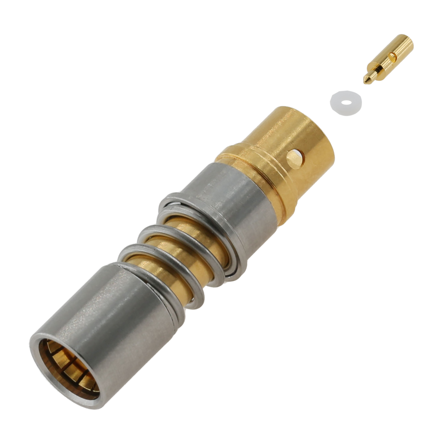
When an RF Connector fails, do not view it as a simple mechanical glitch. Treat it as a severe systemic risk. Component degradation rapidly leads to signal loss, expensive field maintenance, and crippling system downtime. Base metals provide the foundational structural integrity of your hardware. However, the outer plating acts as the frontline defense against oxidation, repeated mating wear, and the high-frequency skin effect.
Specifying the right plating is a vital risk-management decision. It requires you to balance critical electrical performance, environmental durability, and strict project budgets. We will explore how different plating materials behave under high frequencies and harsh conditions. You will learn to navigate complex material trade-offs. This knowledge ensures long-term operational reliability in your network architecture.
Key Takeaways
Plating material directly impacts Passive Intermodulation (PIM), contact resistance, and long-term signal integrity.
High-frequency applications require specific plating profiles (like soft gold or silver) due to the skin effect, where signals travel along the surface of the conductor.
Environmental realities (mating cycles, humidity, salt fog) dictate the necessary hardness and corrosion resistance of the plating layer.
Proper plating specification for board-level components reduces thermal stress and manufacturing defects during soldering.
The Financial and Operational Risks of Substandard Plating
Hardware components inevitably degrade over time in harsh environments. Connectors often seem cheap initially. They represent a tiny fraction of the overall bill of materials. However, they account for a disproportionate percentage of hardware failures. Over a 10-year lifecycle, these microscopic failures drain operational maintenance budgets rapidly. Engineers must recognize this disparity during the initial design phase. Poor material choices lead to compounding field failures later.
Improper plating breaks down rapidly under stress. This breakdown leads to microscopic wear on the contact surfaces. Industry professionals call this destructive process galling. Galling occurs when metals rub together and transfer material. This physical friction increases contact resistance significantly. Increased resistance generates localized heat. Eventually, this physical degradation causes complete signal loss. We often see entire antenna systems fail purely due to unchecked oxidation on a single component.
Passive Intermodulation (PIM) presents another severe operational threat. Ferromagnetic materials naturally generate high PIM levels. Standard nickel falls directly into this magnetic category. PIM disrupts sensitive communication networks aggressively. It creates unwanted signal interference across nearby frequencies. This interference renders entire cellular systems non-compliant. Network operators strictly penalize hardware causing high PIM. You must avoid magnetic plating in critical signal paths completely.
Evaluating Plating Materials for Coaxial RF Connectors: Trade-Offs and Realities
Choosing the correct surface finish requires a deep understanding of material science. Each metal offers unique advantages and distinct physical limitations. You must match the material properties to your specific application environment.
Gold (Hard vs. Soft)
Gold remains the premium standard for high-reliability connections. It provides exceptional corrosion resistance in nearly all environments. It also delivers excellent electrical conductivity and low contact resistance. However, it carries a very high raw material cost. Pure soft gold is highly prone to rapid wear under high mating cycles. Manufacturers often alloy gold with cobalt or nickel to increase hardness. This creates hard gold. Hard gold survives thousands of mating cycles successfully. Gold plating is best for military, aerospace, and high-precision millimeter-wave applications.
Silver
Silver offers the highest electrical conductivity of any metal. It is ideal for high-power and high-frequency transmission tasks. When specifying a coaxial RF connector for heavy-duty base stations, silver excels. However, silver is highly susceptible to tarnishing. It reacts quickly to sulfur in the air. This reaction forms silver sulfide. Silver sulfide complicates soldering processes significantly. Fortunately, this tarnish rarely impacts actual RF performance. Silver remains best for low-PIM base station components and massive transmission lines.
Tri-Metal / White Bronze (Albaloy)
Tri-metal is a specialized alloy. It typically consists of copper, tin, and zinc. It provides excellent wear resistance against repeated mechanical stress. It is completely non-magnetic. This non-magnetic nature ensures exceptionally low PIM performance. Tri-metal is highly tarnish-resistant compared to silver. It serves as a highly cost-effective alternative to pure gold. The only notable drawback is slightly lower electrical conductivity. Tri-metal is best for commercial telecom, 5G deployments, and harsh outdoor environments.
Nickel
Nickel is exceptionally hard and highly durable. It serves as an excellent barrier layer. It prevents underlying base metals from migrating into top precious metal layers. However, nickel possesses strong magnetic properties. These magnetic traits cause massive PIM issues. Therefore, nickel is a poor choice for the primary outer conductor in passive systems. It is best used for non-critical test equipment. It also functions perfectly as an underplate beneath gold or silver.
Plating Material Comparison Matrix
Material
Conductivity
Corrosion Resistance
PIM Performance
Cost Level
Gold
Excellent
Exceptional
Excellent
High
Silver
Superior
Moderate (Tarnishes)
Excellent
Medium
Tri-Metal
Good
Excellent
Excellent
Low-Medium
Nickel
Moderate
Excellent
Poor (Magnetic)
Low
Overcoming High-Frequency and 5G Signal Degradation
High-frequency applications demand extreme precision. Standard low-frequency design rules no longer apply in the gigahertz spectrum. You must optimize the outer conductive layer meticulously.
The skin effect is a fundamental physical reality. At high frequencies, electrical currents do not penetrate the entire conductor. Instead, they travel almost exclusively on the outer skin of the connector contact. In the GHz range, the active conductive depth shrinks to mere micrometers. Therefore, the base metal handles very little current. The plating material performs almost the entire electrical transmission task. You must prioritize the electrical properties of the plating finish above all else.
Plating thickness requires careful calculation. Thicker plating is not always better. Excessive thickness alters mechanical tolerances. It also wastes expensive materials. You must detail the necessity of calculating minimum plating thickness. This minimum thickness must accommodate the specific skin depth at your target operating frequencies. If the plating is too thin, the signal penetrates into the poorly conducting base metal. This penetration causes massive insertion loss.
Skin Depth Reference Chart
Frequency
Approximate Skin Depth (Gold)
Approximate Skin Depth (Silver)
1 GHz
2.4 micrometers
2.0 micrometers
10 GHz
0.75 micrometers
0.64 micrometers
30 GHz
0.43 micrometers
0.37 micrometers
Surface roughness plays a critical role in signal integrity. Poor plating processes create microscopic surface irregularities. High-frequency signals must travel over these tiny bumps and valleys. This irregular topography effectively lengthens the electrical path. A longer path leads directly to increased insertion loss. Furthermore, uneven surfaces cause severe phase distortion in delicate high-frequency applications. You must specify maximum surface roughness tolerances strictly.
Integration Realities: Specifying an RF Connector for PCB Applications
Board-level integration introduces entirely new mechanical challenges. The connector must survive the aggressive PCB assembly process. It must maintain perfect electrical performance afterward.
Solderability and thermal stress management are paramount. When selecting an RF connector for PCB mounting, the plating must withstand extreme heat. Reflow soldering temperatures routinely exceed 260 degrees Celsius. Substandard plating fails catastrophically under this thermal stress. It will blister instantly. It may also delaminate entirely from the base metal. These defects ruin the mechanical bond. They also destroy the electrical connection permanently.
Mitigating base metal migration requires engineering foresight. Metals become highly active at elevated soldering temperatures. Common base metals like zinc or brass will migrate upwards. They will diffuse directly into the top gold or silver plating. This diffusion ruins the solder joint integrity completely. You must require a proper underplate. A dense nickel layer blocks this migration perfectly. Specialized copper alloys also serve as effective diffusion barriers for non-magnetic applications.
Automated assembly considerations heavily influence plating choices. High-volume manufacturing relies on optical pick-and-place machines. Consistent plating thickness and visual composition are vital here. Vision systems reject components showing inconsistent surface colors. Uneven plating also causes components to sit improperly on solder pads. Controlling the plating uniformity reduces assembly rejection rates massively. It ensures your production lines run without costly interruptions.
Framework for Shortlisting Vendors and Validating Plating Quality
Trusting a vendor blindly is a dangerous engineering practice. You must validate their plating capabilities through strict auditing and objective testing.
Audit the Manufacturing Process: Look for vendors controlling the electroplating process in-house. In-house control ensures rapid quality adjustments. If they outsource, demand strict oversight documentation. Traceable oversight of their plating partners prevents contaminated batches. Ask about their chemical bath maintenance schedules.
Requesting Evidence: Demand objective testing data before signing contracts. Ask for official salt spray test results strictly following ASTM B117 standards. Require certified PIM ratings for your specific frequency bands. Ask for specific mating cycle guarantees. Reliable vendors provide this data eagerly.
Prototyping Next Steps: Never commit to full-scale production immediately. Recommend ordering small sample runs first. Subject these samples to rigorous environmental chamber testing. Perform thermal shock evaluations to verify adhesion quality. Evaluate the solderability on your actual assembly line.
Vendors cutting corners on plating baths will fail these basic tests. Prioritize partners demonstrating transparent quality control procedures. Ask to review their internal inspection logs. Proper validation upfront saves massive redesign headaches later.
Conclusion
Plating is a highly functional engineering requirement. It is never a simple cosmetic afterthought. The exact material you choose dictates the survival of your network hardware. A well-specified finish combats oxidation, survives thermal stress, and optimizes high-frequency signal flow.
Remember these critical next steps. First, match your plating hardness to your expected mating cycles. Second, always calculate skin depth requirements for high-frequency operations. Third, demand strict diffusion barrier layers for PCB-mounted components. The right choice prevents compounding failures down the line. We strongly recommend consulting directly with an application engineer. Review your exact environmental requirements, frequency range, and PIM specifications together. They will help you receive a fully customized, highly reliable connector recommendation.
FAQ
Q: Why can't I just use gold plating for every RF connector?
A: While gold offers premium conductivity and corrosion resistance, it is prohibitively expensive for large-scale commercial deployments. Additionally, pure soft gold can suffer from premature wear in applications requiring frequent mating cycles unless it is specifically alloyed for hardness.
Q: How does plating thickness affect mating cycles?
A: Thicker plating generally increases durability and extends the lifespan of the contact point. However, excessive thickness can alter the mechanical tolerances of the connector. This causes severe fitment issues or dangerously increased insertion force during mating.
Q: What is the best plating for low-PIM requirements?
A: Tri-metal (White Bronze) and Silver are the definitive industry standards for low-PIM applications. They excel because they are entirely non-magnetic materials. They do not generate the harmful intermodulation interference common to magnetic underplates like Nickel.
Q: How do environmental factors dictate plating choice?
A: Applications exposed to high humidity, salt fog, or corrosive industrial gases require non-porous materials. You must use highly stable plating formulations like Tri-metal or specific hard Gold alloys. These specific finishes prevent aggressive base metal corrosion effectively.
Our company, Zhejiang LenoRF Industry co. LTD, occupies an area of 30 hectares and is equipped with world class equipment to make millimeter wave connectors and phase stable cables. We specialize in coaxial connectors, cable assembly, and passive devices. Our current products are the latest millimeter wave connector and phase stable cable on the market.