The return loss (VSWR) of the RF connector is a significant characteristic in the RF business, and achieving a low return loss is our primary priority.
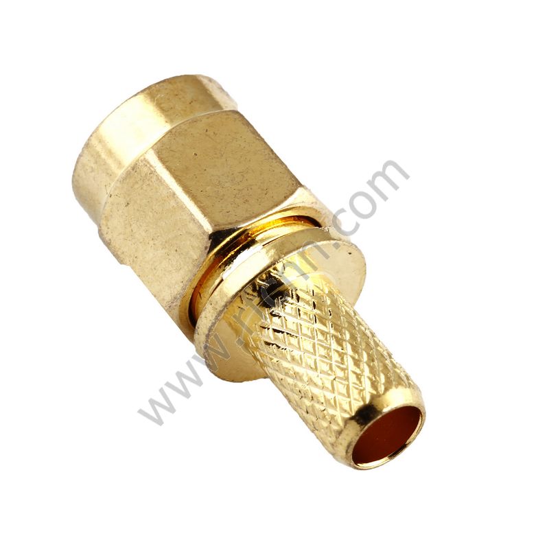
For connectors built with cable, such as SMA plug crimping for RG174, we test the connector with an RG174 using a vector network analyzer.
We may immediately test the RF adapter using a vector network analyzer.
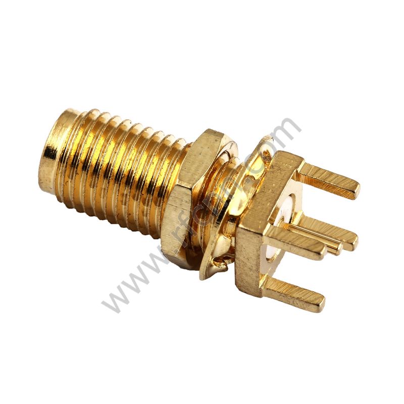
But how do we test the PCB type of an RF connector?
We have two solutions for test these kind of connectors.
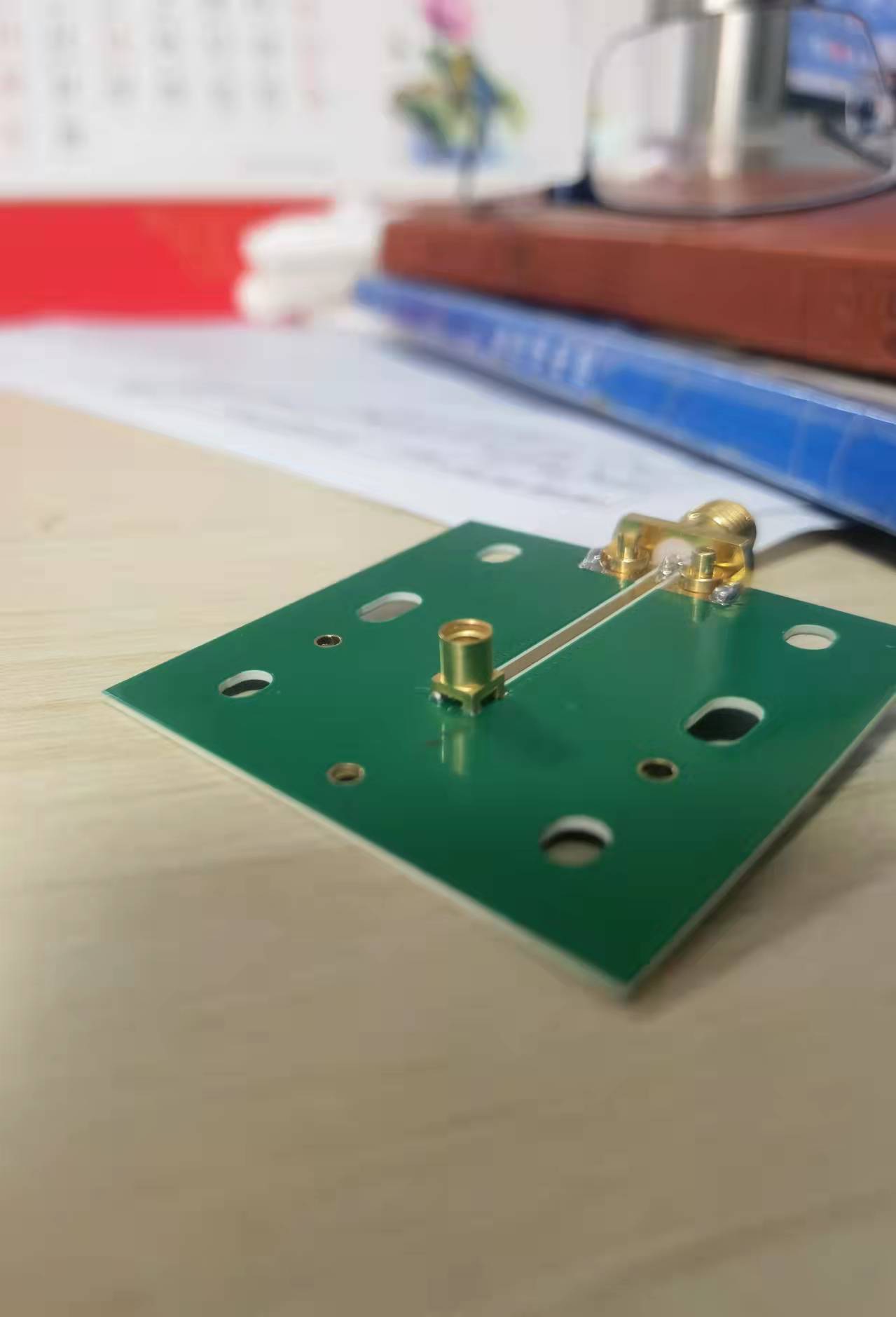
Solution one:
LenoRF designed a typical test PCB board with 50 OHMS. This PCB uses a special board material to get a higher dielectric constant; the popular brand is Rogers, and the board material is ceramic or PTFE. The end user will be able to easily test the return loss.
Solution two:
Another option is to create a fixtures that will hold two SMA connectors together and act as a SMA adapter. This fixture must be very exact, or else some errors will arise owing to contact resistance and bad contact.
Our company, Zhejiang LenoRF Industry co. LTD, occupies an area of 30 hectares and is equipped with world class equipment to make millimeter wave connectors and phase stable cables. We specialize in coaxial connectors, cable assembly, and passive devices. Our current products are the latest millimeter wave connector and phase stable cable on the market.