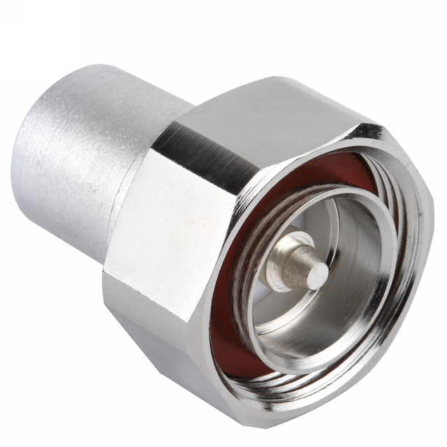
An RF terminator is a controlled load placed at the end of a transmission line, unused port, test path, or active RF output. Its job is simple in principle: present the intended impedance and absorb incident RF energy with minimal reflection. In practice, choosing one requires more than selecting a 50 Ohm label. Frequency range, power condition, connector series, VSWR, cooling, mounting, and the difference between a protective cap and a power-capable load can determine whether the terminator improves a system or becomes its weak point. This guide explains how to select RF terminators for microwave systems, test benches, communication hardware, and production fixtures.
Key Takeaways
A 50 Ohm terminator is the standard choice for most RF and microwave signal paths, but 75 Ohm and 93 Ohm systems also exist.
The load’s rated power must match the actual CW, pulsed, average, and mismatch conditions—not only a nominal transmitter wattage.
Connector type sets mechanical compatibility and can limit the usable frequency and power of the assembled interface.
A termination reduces reflections only when its impedance and frequency behavior match the system.
Treat the terminator as an RF component: inspect mating surfaces, use correct torque, and allow for heat dissipation.
What an RF Terminator Does
An RF terminator, also called an RF load, coaxial terminator, or dummy load in some contexts, absorbs RF energy at the end of a line. Ideally, its impedance equals the system characteristic impedance. When a 50 Ohm RF load is connected to a 50 Ohm source and 50 Ohm transmission line, the impedance match minimizes reflected energy. This helps protect active equipment, stabilize measurements, and prevent an open port from changing the behavior of a network.
The familiar relationship is expressed in plain text as reflection coefficient = (load impedance - system impedance) / (load impedance + system impedance). When the two impedances are equal, the ideal reflection coefficient is zero. Real components are not ideal, especially as frequency rises, which is why a terminator datasheet includes a frequency range and VSWR or return-loss specification.
Terminations appear in many places: unused ports of a power divider or coupler, the output of an amplifier during setup, a spare antenna port, a calibration fixture, and a test instrument connection. Each use has a different power and accuracy requirement. A small SMA terminator that is appropriate for a low-level VNA port may be unsafe on a power-amplifier output.
50 Ohm, 75 Ohm, and 93 Ohm: Match the System First
Fifty ohms is common in RF, microwave, test, wireless, radar, and many communication applications because it balances power handling and loss considerations in coaxial systems. Seventy-five ohms is common in video and some broadcast or cable contexts. Ninety-three ohms is used in selected legacy and specialized systems. The right terminator is the one that matches the characteristic impedance of the line and equipment—not simply the most available stock item.
LenoRF lists RF terminators in 50 Ohm, 75 Ohm, and 93 Ohm versions, with low-, medium-, and high-power RF load categories. The category also states frequency ratings reaching DC to 50 GHz across its range. This does not mean every product covers every value; always verify the individual part’s frequency, connector, power, and environmental specification.
Selection factor
Why it matters
Questions to ask before ordering
Impedance
A mismatch creates reflections and can alter source/load performance.
Is the system 50 Ohm, 75 Ohm, or another defined impedance?
Frequency range
Parasitics and connector geometry affect match at high frequency.
What is the highest operating or harmonic frequency?
Power rating
Absorbed RF energy turns into heat.
Is the rating CW, peak, average, or pulsed? What is the duty cycle?
Connector type
It must mate mechanically and perform electrically at the intended band.
SMA, Type N, 2.92 mm, 3.5 mm, BNC, or another series?
VSWR/return loss
Quantifies match quality over a stated range.
Is the limit guaranteed throughout the required band?
Mechanical and thermal design
Heat, vibration, torque, and mounting determine reliability.
Does it need a heat sink, panel mount, chain, or weather protection?
Power Ratings: The Most Important Safety Check
Power rating is where many RF termination mistakes begin. Every watt absorbed by a load becomes heat. A resistor element, dielectric, connector interface, and housing all have temperature limits. The rating may assume a defined ambient temperature, free-air mounting, forced air, a heat sink, or a short pulse. Without those conditions, a wattage label is incomplete.
Start by deciding whether the signal is continuous wave or pulsed. For a simple pulse train, average power equals peak power times duty cycle. For example, a 1,000 W pulse at a 1 percent duty cycle has an idealized 10 W average power. Yet that does not prove a 10 W terminator is acceptable: the element must withstand the peak voltage and current, the pulse width, repetition behavior, and transient heating. Use the manufacturer’s pulsed-power limits rather than trying to infer them from an average-only rating.
Mismatch can increase the stress further. A load that is not perfectly matched reflects power back toward the source and may experience a nonuniform voltage/current distribution. Therefore choose margin not only for nominal output but for the actual VSWR, modulation, ambient temperature, and duration. When validating an amplifier on the bench, use a load designed for that power and band, and make sure its cooling surface is not blocked.
Frequency Limits and VSWR
An RF terminator is not an ideal resistor placed in a schematic. At microwave frequencies, the shape of the resistor, the transition into the connector, the dielectric, and the enclosure all affect impedance. A terminator can be excellent at a few gigahertz and less well matched near its upper-frequency rating. The stated maximum frequency is therefore a performance boundary, not simply a mechanical compatibility number.
VSWR, or voltage standing wave ratio, is a common way to express mismatch. A lower VSWR indicates a better match. Return loss expresses the same phenomenon on a logarithmic dB scale. It is useful to evaluate the specification at the full operating interval. A typical value near the center of the band should not replace a guaranteed maximum at the system’s highest frequency.
Use a VSWR-versus-return-loss conversion when comparing device specifications. Treat the result as a design aid; then assess the total reflection behavior of cables, adapters, connectors, and the load together.
Connector Types and Their Practical Consequences
Connector selection begins with compatibility, but should end with a bandwidth and power check. SMA terminators are compact and common in laboratory and microwave systems. Type N can be useful where a larger, more rugged interface is appropriate. Precision connectors such as 3.5 mm, 2.92 mm, 2.4 mm, and 1.85 mm support higher-frequency work when correctly specified and handled. BNC and TNC may suit other frequency ranges and mechanical needs.
Do not connect a precision high-frequency port to a lower-performance interface with an adapter merely because it can be mated. The adapter may reduce the usable frequency, raise reflections, introduce an incompatible gender arrangement, or create a mechanical stack that is vulnerable to damage. Define compatible connector categories across the system.
Gender terms can also be confusing. “Male/female” and “plug/jack” are often used, but connector-series conventions do not always map cleanly to a visual intuition about center contacts. Confirm the manufacturer’s mating description and part drawing. An incorrect gender selection can delay a build; forcing a mating interface can damage expensive precision connectors.
Low-Power Versus High-Power RF Loads
Low-power loads are often compact, connector-mounted parts used for unused ports, calibration paths, instrument interfaces, and low-level measurements. Their convenience makes them easy to overlook, but their small physical size limits heat dissipation. They should never be assumed to protect an amplifier output.
Medium- and high-power RF loads usually have larger metal bodies, heat sinks, fins, panel mounts, or provisions for forced-air or liquid cooling. They may use larger connector series and need a secure mechanical mounting scheme. The RF path must be arranged so the component can cool as specified. A high-power load mounted against an insulating surface or placed in stagnant air may rapidly exceed its rating even when the input power appears compliant.
For production or field hardware, consider whether the termination is permanently installed or only used during service. Permanent terminations need appropriate vibration, corrosion, ingress, and strain-relief planning. Service loads need clear labeling so they are not mistakenly used beyond their rated band or power. Plan the load and the connection path together.
Selecting an RF Terminator Step by Step
First, identify the line impedance and connector interface. Second, define the frequency range including harmonics or test-sweep headroom. Third, calculate the maximum incident RF condition: continuous, average, peak, pulse width, duty cycle, and expected mismatch. Fourth, select the required VSWR/return-loss target. Fifth, check environmental and mechanical requirements, including cooling and mounting.
Next, examine the actual assembly. If a high-power amplifier output reaches the terminator through a cable, the cable also needs sufficient power rating and an acceptable loss budget. If adapters are used, include their frequency and VSWR in the analysis. Tighten threaded interfaces to the manufacturer’s recommended torque and avoid side loads from stiff cables. Clean, undamaged mating surfaces are critical at microwave frequencies.
Finally, establish a test procedure. Before applying high power, verify the selected terminator part, connector mating, cooling condition, and power-meter or directional-coupler setup. Increase power under observation when feasible, following the equipment’s safe operating procedure. This process is simple compared with recovering from a damaged amplifier output stage.
Common RF Termination Errors
The first error is using the wrong impedance because 50 Ohm components are more common. The second is selecting a power rating based only on average power while ignoring peak conditions, duty cycle, and ambient. The third is choosing a connector for fit rather than frequency performance. The fourth is assuming a terminator’s rated frequency applies through any adapter stack.
Another mistake is treating a terminator as a passive afterthought in a high-power system. It is an energy-absorbing device with thermal requirements. Document the part number, its approved operating conditions, and its location in the RF chain. If it is a critical protection component, provide a clear inspection and replacement interval. This is especially important where maintenance staff may encounter visually similar loads with very different ratings.
Conclusion
An RF terminator protects performance by giving unused ports, test paths, and RF outputs the impedance they expect. The correct choice starts with system impedance, then verifies frequency range, power condition, VSWR, connector type, and thermal installation. A 50 Ohm label is only the beginning of that process.
LenoRF offers RF terminator categories alongside connectors and cable assemblies that can support a complete RF interconnect design. Use the individual product specification for the final selection, apply enough thermal and power margin, and validate the assembled path. That disciplined approach keeps the RF load from becoming the limiting component in an otherwise capable microwave system.
FAQs
What is a 50 Ohm terminator used for?
A 50 Ohm terminator provides a matched load for a 50 Ohm RF system. It is commonly used on unused ports, test equipment, power dividers, couplers, antenna paths, and amplifier outputs during controlled setup.
Is an RF terminator the same as a dummy load?
The terms often overlap. A dummy load usually emphasizes absorbing transmitter or amplifier power, while an RF terminator may also describe low-power matched loads used on ports and measurement equipment. Check the actual power and frequency rating.
Can I use a 50 Ohm terminator in a 75 Ohm system?
No, not when a proper match is required. A 50 Ohm load in a 75 Ohm system introduces a mismatch and reflections. Select a termination that matches the system’s characteristic impedance.
How do I choose the power rating of an RF load?
Use the maximum expected RF condition and consider CW versus pulse behavior, duty cycle, VSWR, ambient temperature, cooling, and duration. Follow the manufacturer’s specific ratings and derating guidance.
Does connector type affect terminator frequency range?
Yes. Connector geometry and the transition into the load affect high-frequency performance. The terminator and every adapter in the path must be rated for the intended band.
Why does a high-power RF load get hot?
It converts incident RF power into heat. The housing and mounting must dissipate that heat according to the load’s specified cooling conditions.
Our company, Zhejiang LenoRF Industry co. LTD, occupies an area of 30 hectares and is equipped with world class equipment to make millimeter wave connectors and phase stable cables. We specialize in coaxial connectors, cable assembly, and passive devices. Our current products are the latest millimeter wave connector and phase stable cable on the market.