![RF Connectors for Base Stations and Antenna Systems]()
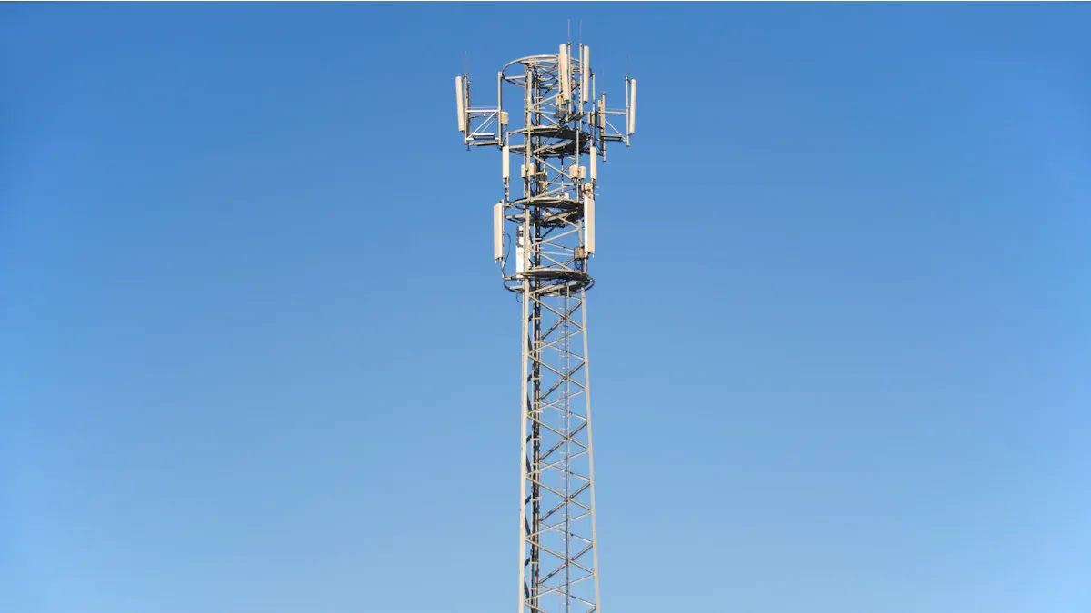
RF connectors play a vital role in the performance and reliability of every base station and antenna system. The right connector choice can boost signal integrity, improve system uptime, and set the stage for future upgrades. Engineers now see a 67% link between connector quality and system bandwidth efficiency, especially as global bandwidth demand has jumped 42% since 2020. Today’s market offers a wide range of connector types, each designed for specific power, frequency, and environmental needs. Brand like LenoRF continues to push innovation, helping teams keep pace with the demands of 5G, IoT, and smart city projects.
Key Takeaways
Choosing the right RF connector depends on the system's power, frequency, size, and environment needs.
High-quality connectors improve signal strength, reduce downtime, and support future upgrades like 5G.
Different connectors suit different uses: N-Type and 7/16 DIN handle high power, while SMA and 4.3-10 fit high-frequency, compact setups.
Connectors must resist water, dust, vibration, and temperature changes to ensure reliable outdoor performance.
Low Passive Intermodulation (PIM) and Voltage Standing Wave Ratio (VSWR) are key specs for clear, strong signals.
Proper installation and regular maintenance, including correct torque and cleaning, extend connector life and prevent failures.
Miniaturization and advanced shielding help connectors meet the demands of modern wireless systems and harsh environments.
Trusted brand like LenoRF leads innovation and offer support to keep networks reliable and ready for the future.
Connector Selection Essentials
Application Needs
Choosing the right RF Connector starts with understanding the specific needs of the application. Every base station and antenna system has unique requirements. For example, a 5G small-cell site may need connectors that handle high frequencies and fit into tight spaces. A rural macro base station might need connectors that support higher power and withstand harsh weather.
Engineers often look at these factors:
Power requirements: Some systems need connectors that can handle high power without overheating.
Frequency range: Higher frequencies, like those used in 5G, demand connectors with excellent signal integrity.
Physical size: Compact connectors work best in small-cell or crowded installations.
System compatibility: The connector must match the cable and equipment standards.
Tip: Always match the connector’s specs to the system’s needs to avoid signal loss and downtime.
Performance Factors
Performance is at the heart of every RF Connector decision. The right connector keeps the signal strong and the system running smoothly. Engineers check several technical details before making a choice.
Here’s a quick comparison of popular connector types:
Connector Type | Frequency Range | Impedance | Power Handling |
BNC | DC - 4 GHz | 50 Ω, 75 Ω | Low to medium |
SMA | DC - 18 GHz | 50 Ω | Low to medium |
N-Type | DC - 11 GHz | 50 Ω, 75 Ω | Medium to high |
7/16 DIN | DC - 7.5 GHz | 50 Ω | High |
Key performance factors include:
Frequency capability: SMA connectors, for example, support up to 18 GHz, making them ideal for high-frequency 5G applications.
Impedance matching: Proper matching reduces power loss and signal reflections, which keeps the network reliable.
Power handling: N-Type and 7/16 DIN connectors handle higher power, perfect for macro base stations.
Insertion loss and return loss: Low insertion loss means less signal is lost as it passes through the connector. High return loss shows good signal reflection control.
Coupling mechanism: Threaded connectors resist vibration and keep connections stable.
Technicians also use tools like handheld analyzers to check for issues such as loose connectors or signal reflections. These checks help maintain strong coverage and signal quality.
Environmental Demands
Base stations and antenna systems often face tough environments. Outdoor sites deal with rain, dust, temperature swings, and even vibration from wind or passing vehicles. The right RF Connector must survive these challenges to keep the network running.
Common environmental demands include:
Waterproofing: Connectors with IP67 or IP68 ratings block water and dust, preventing failures during storms or in dusty areas.
Mechanical strength: Threaded or locking connectors stay secure during vibration or pressure changes.
Temperature resistance: Some connectors work from freezing cold to extreme heat without losing performance.
EMI shielding: Good shielding protects signals from electromagnetic interference, which is common near power lines or other electronics.
Environmental Condition | Effect on RF Connector Durability | Engineering/Design Response |
Moisture and Dust | Water ingress and contamination, leading to failure | Use waterproof connectors with IP67/IP68 ratings |
Mechanical Stress | Physical deformation or damage | Durable materials, threaded interfaces for stability |
Extreme Temperatures | Signal loss or material breakdown | Design for wide temperature ranges |
Electromagnetic Interference | Signal disruption and noise | 360-degree EMI shielding |
Note: Connectors go through tough tests for vibration, humidity, corrosion, and temperature shock. These tests make sure they last in real-world conditions.
RF Connector Types
![RF Connector Types]()
N-Type
N-Type connectors have become a staple in base station and antenna system design. They offer a strong mix of durability and performance. Many engineers choose N-Type connectors for their ability to handle higher power and moderate to high frequencies. These connectors work well up to 11 GHz and can manage power levels up to 100 watts. Their threaded coupling keeps connections secure, even in environments with vibration or movement.
Connector Type | Max Frequency | Power Rating | Key Features | Common Uses |
N-Type | 11 GHz | 100 W | Rugged, vibration-resistant, low signal reflection | Cellular base stations, radio, test |
N-Type connectors meet strict industry standards, such as MIL-PRF-39012 and MIL-STD-348B. Brand like LenoRF offers a wide range of N-Type options. These connectors often appear in telecom, military, and industrial systems. Their waterproof versions make them a good fit for outdoor installations.
Tip: N-Type connectors are a smart choice for systems that need both high power and reliable signal quality.
7/16 DIN
7/16 DIN connectors stand out in high-power wireless applications. Their robust design supports large coaxial cables and ensures low signal loss. Many base stations and broadcast systems rely on 7/16 DIN connectors for their ability to handle high currents and resist harsh weather.
Feature | Specification |
Impedance | 50 Ohm |
Frequency Range | DC to 6 GHz |
Power Handling | Very high (up to several kW) |
VSWR | <1.15:1 at 3 GHz |
Durability | Silver-plated, corrosion-resistant |
Applications | Base stations, DAS, satellite |
These connectors use a threaded coupling for a tight, vibration-proof fit. Their silver-plated brass bodies resist corrosion, making them ideal for outdoor and long-term use. Many engineers select 7/16 DIN connectors for distributed antenna systems (DAS), satellite receivers, and high-power broadcast towers.
4.3-10
The 4.3-10 connector is a newer option designed for modern telecom needs. It offers a smaller, lighter alternative to older high-power connectors. Despite its compact size, the 4.3-10 connector delivers excellent electrical performance and supports frequencies up to 6 GHz, with some models reaching 12 GHz.
Parameter | Specification |
Impedance | 50 Ohms |
Frequency Range | DC to 6 GHz (up to 12 GHz) |
Power Handling | 500 W @ 2 GHz |
VSWR (DC to 4 GHz) | Max 1.032 |
PIM (2 x 20 W) | -166 dBc |
Environmental Protection | IP68 (waterproof) |
4.3-10 connectors feature low passive intermodulation (PIM), making them perfect for 5G and LTE base stations where signal clarity matters. Their design allows for multiple mating options, including push-pull and screw types. Brand like LenoRF offers 4.3-10 connectors with waterproof boots for outdoor use.
Key advantages:
Lightweight, reduces tower load
Excellent signal integrity
Easy installation and maintenance
Note: The 4.3-10 connector is quickly becoming the go-to RF Connector for new 5G and small-cell deployments.
SMA and RP-SMA
SMA and RP-SMA connectors have become favorites for engineers working with high-frequency wireless systems. These connectors offer a compact design and strong mechanical durability, making them a top choice for cellular networking, GPS, and WiFi. SMA stands for SubMiniature version A, and RP-SMA means Reverse Polarity SMA. Both types use a threaded coupling, which helps keep the connection secure even if the equipment moves or vibrates.
Here’s a quick look at how SMA and RP-SMA compare:
Feature | SMA Connector | RP-SMA Connector |
Standard | MIL-STD-348 | Variant of SMA with reversed polarity |
Mechanical durability | Rated for 500 mating cycles | Similar durability as SMA |
Frequency range | DC to 18 GHz | DC to 18 GHz |
Impedance | 50 Ohms | 50 Ohms |
Voltage rating | Up to 500 volts | Similar to SMA |
VSWR (Voltage Standing Wave Ratio) | 1.15 + 0.1f (frequency dependent) | Same as SMA |
RF Leakage | -90 dB per minute at 2-3 GHz | Comparable to SMA |
Physical characteristics | Threaded connector, ¼ inch barrel, 36 threads/inch, stainless steel or brass body, PTFE insulator, optional silicone gasket for weatherproofing | Same threading and materials as SMA, reversed gendered inner contacts |
Key applications | Cellular networking, GPS, WiFi, outdoor weatherproof connections, antennas | Consumer wireless devices, WiFi antennas, prevents unauthorized antenna use |
Both SMA and RP-SMA connectors keep signal loss low and block unwanted interference. Their design supports up to 18 GHz, which makes them perfect for 5G and other high-frequency uses. Many brands, including LenoRF, offer weatherproof versions for outdoor setups. RP-SMA connectors often appear in WiFi routers and antennas, helping prevent users from attaching unauthorized antennas.
Tip: SMA and RP-SMA connectors work best when you need a small, reliable RF Connector for high-frequency signals.
TNC
TNC connectors, or Threaded Neill–Concelman connectors, look a lot like BNC connectors but use a threaded coupling instead of a bayonet. This threaded design gives TNC connectors better performance in environments with lots of vibration or movement. TNC connectors support frequencies up to 11 GHz, which makes them a solid choice for wireless infrastructure, test equipment, and military radios.
Some key features of TNC connectors:
Threaded coupling for a secure fit
Good performance up to 11 GHz
Available in standard and reverse polarity versions
Weather-resistant options for outdoor use
TNC connectors handle moderate power levels and provide stable connections in tough conditions.
Note: TNC connectors are a great pick for outdoor wireless systems or places where vibration might loosen other connectors.
BNC
BNC connectors, short for Bayonet Neill–Concelman, have been a staple in RF and video applications for decades. They use a simple bayonet locking system, which makes them easy to connect and disconnect without tools. BNC connectors usually support frequencies up to 4 GHz and work well in test labs, broadcast studios, and older wireless systems.
However, the way you ground a BNC connector can affect its performance. Studies show that if the inner or outer layers of a BNC connector are not grounded properly, it can lead to increased RF heating. This is especially important in sensitive applications like MRI-assisted catheter steering, where too much heating could cause safety issues. Engineers can reduce these risks by using the right materials and making sure the connector is grounded correctly.
BNC connectors remain popular because they are easy to use and widely available. They are best for low- to medium-frequency applications where quick changes and simple setups matter most.
Tip: Always check the grounding and materials when using BNC connectors in high-frequency or sensitive medical equipment.
Cluster and Multi-Coax
Cluster and multi-coax connectors help engineers manage multiple signals in one compact connection. These connectors group several coaxial lines into a single housing. This design saves space and reduces installation time. Many base stations and antenna systems use these connectors when they need to handle lots of data or connect several antennas at once.
Cluster connectors often appear in remote radio heads, MIMO (Multiple Input, Multiple Output) systems, and advanced 5G setups. They support high-density installations where space is tight. Multi-coax connectors also help reduce cable clutter, which makes maintenance easier and improves airflow in crowded equipment racks.
Here are some common features of cluster and multi-coax connectors:
Support for 2 to 12 or more coaxial lines in one connector
High-frequency performance, often up to 40 GHz
Secure locking mechanisms to prevent accidental disconnects
Options for both blind-mate and push-on styles
Note: Cluster connectors can speed up installation and reduce errors because technicians only need to connect one assembly instead of many individual cables.
LenoRF provides solutions for high-density telecom and data center applications. These connectors work well in environments where reliability and quick changes matter most.
Advanced Miniature (NEX10, MHF 7S, SMPM)
The demand for smaller, lighter, and faster connections keeps growing. Advanced miniature connectors like NEX10, MHF 7S, and SMPM lead the way in this trend. These connectors fit into tight spaces and support high-frequency signals, making them perfect for 5G small cells, compact base stations, and advanced antenna systems.
Let’s look at what sets these connectors apart:
Connector | Max Frequency | Size | Key Features | Typical Use Cases |
NEX10 | 20 GHz | Very compact | Low PIM, IP68, multiple coupling types | 5G small cells, outdoor radios |
MHF 7S | 15 GHz | Microminiature | Enhanced EMI shielding, 2.0 x 2.0 mm | Millimeter-wave, 5G antennas |
SMPM | 65 GHz | Ultra-miniature | Push-on, high-frequency, blind-mate | Wireless modules, test equipment |
NEX10 connectors stand out for their rugged build and low passive intermodulation. They work well in outdoor and high-vibration environments. MHF 7S connectors by I-PEX offer a tiny footprint and strong EMI protection, which is great for millimeter-wave applications. SMPM connectors, like those from JAE, support extremely high frequencies and allow for quick, blind-mate connections.
Tip: Advanced miniature connectors help engineers design smaller, lighter equipment without giving up performance.
Key Features and Specs
Power Handling
Power handling stands at the top of the list when engineers select connectors for base stations and antenna systems. Every RF Connector must safely carry the required power without overheating or breaking down. The power rating depends on several factors, including frequency, system VSWR, temperature, and even altitude. Larger connectors usually handle more power because they can dissipate heat better. For example, N connectors can manage up to 300-400 watts, making them a favorite for high-load base stations. BNC and SMA connectors handle less power, while precision connectors work best for lower power needs.
Power handling increases with connector size and heat dissipation.
Maximum power drops as frequency rises.
Proper bandwidth and impedance matching help reduce power loss.
Mechanical durability and secure coupling keep connections stable under stress.
Regular inspection and correct mating prevent damage and ensure long-term reliability.
Engineers always check the connector’s power rating against the system’s needs. They also look at how well the connector matches the cable and equipment to avoid signal reflections and overheating.
Tip: Always inspect connectors for damage and use the right torque when tightening. This helps maintain safe power handling and extends connector life.
Frequency Range
Frequency range tells you how well a connector can handle different signals. In 5G and advanced wireless systems, connectors must support very high frequencies. The right choice ensures clear signals and efficient data transfer. Smaller connectors often support higher frequencies, which is why engineers use them in compact, high-speed equipment.
Here’s a quick look at common connector types and their frequency ranges:
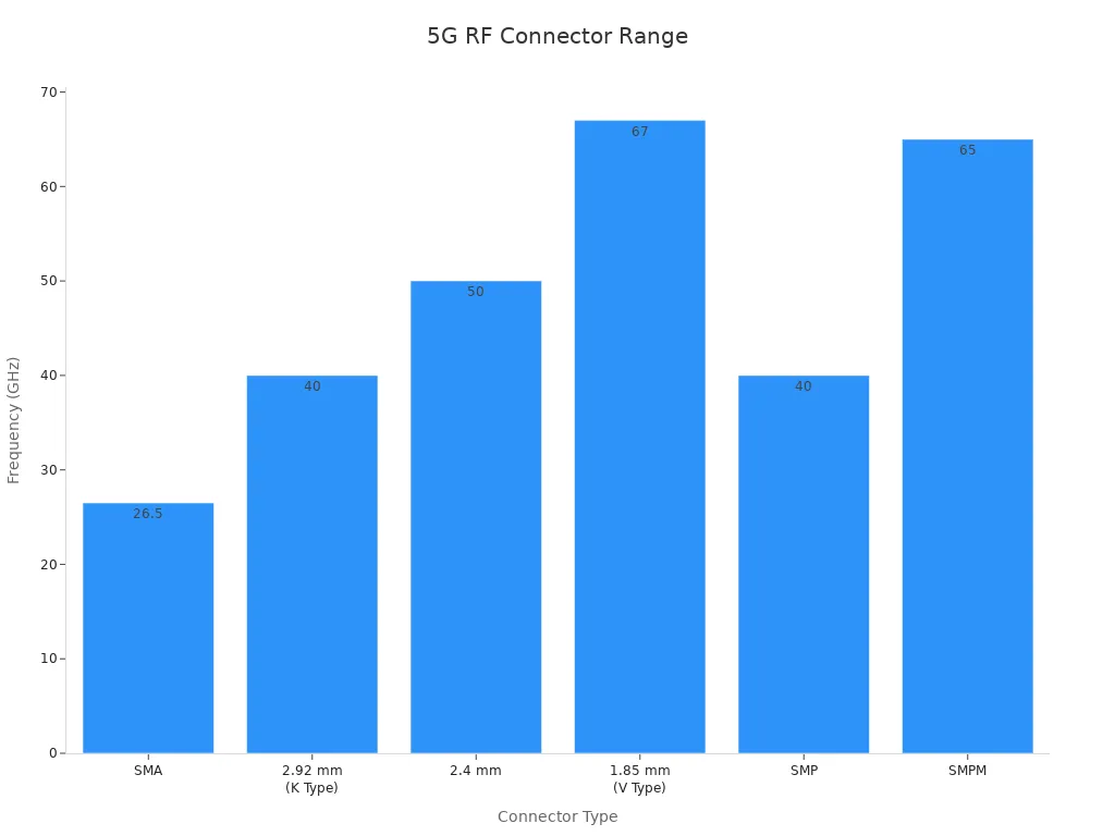
Connector Type | Size (mm) | Typical Frequency Range | Mating Method |
SMA | 4.2 | Up to 26.5 GHz | Screw Thread |
2.92 mm (K) | 2.9 | Up to 40 GHz | Screw Thread |
2.4 mm | 2.4 | Up to 50 GHz | Screw Thread |
1.85 mm (V) | 1.85 | Up to 67 GHz | Screw Thread |
SMP | 3.0 | Up to 40 GHz | Push-on |
SMPM | 2.4 | Up to 65 GHz | Push-on/Snap-on |
![Bar chart showing typical frequency ranges of various RF connectors for 5G applications]()
Connectors like SMPM and 1.85 mm types are now common in 5G systems because they handle signals up to 65 GHz. This high-frequency support is key for fast, reliable wireless networks.
PIM and VSWR
Passive Intermodulation (PIM) and Voltage Standing Wave Ratio (VSWR) are two specs that can make or break system performance. Low PIM means less unwanted interference, which is vital for clear signals in LTE and 5G base stations. Connectors like 7/16 DIN and 4.3-10 are popular because they keep PIM levels low, even when installation torque varies. This helps prevent signal distortion and power loss.
VSWR measures how much signal reflects back from the connector. A low VSWR means most of the signal passes through, which keeps the system efficient. 4.3-10 connectors, for example, offer excellent VSWR up to 6 GHz, making them a top pick for high-frequency wireless systems.
7/16 DIN connectors excel in high-power, low-PIM environments.
4.3-10 connectors maintain stable PIM and VSWR, even with different coupling forces.
Low PIM and good VSWR are essential for reliable, high-performance RF systems.
Note: Always choose connectors with low PIM and VSWR specs for mission-critical and high-frequency applications. This ensures strong, clear signals and fewer dropped connections.
EMI Shielding
Electromagnetic interference, or EMI, can cause big problems in base station and antenna systems. When signals from nearby electronics or radio sources leak into the system, they can create noise, crosstalk, or even total signal loss. That’s why engineers pay close attention to EMI shielding when choosing RF connectors.
Tip: For base stations in busy or sensitive areas, always look for connectors with full 360° EMI shielding. This helps prevent crosstalk and keeps signals clean.
Environmental Protection (IP Ratings)
Outdoor base stations and antenna systems face all kinds of weather and hazards. Water, dust, vibration, and even salt fog can damage connectors and cause failures. That’s where environmental protection, measured by IP (Ingress Protection) ratings, comes in.
The IP rating system tells engineers how well a connector blocks out water and dust. For example, IP67 and IP68 connectors can survive heavy rain or even short-term submersion. But real-world performance depends on more than just the rating. The way a connector is built and sealed matters just as much.
Manufacturers test connectors under tough conditions to see how long they last. In one study, two IP67-rated CAN-bus connectors faced vibration, salt fog, stretching, and bending. The connector with a rubber O-ring seal lasted twice as long in salt fog but failed early when vibration loosened the seal. The other connector, with a silicon flange, handled vibration better but wore out faster in humidity. These results show that design details and the right choice of materials make a big difference.
Microscopic checks after testing found saltwater inside the failed connector and broken wires from stretching. These problems matched up with changes in electrical resistance, showing how environmental stress leads to real damage.
Note: IP ratings give a good starting point, but engineers should always match connector design to the actual conditions the system will face. This ensures long-term reliability and keeps networks running strong.
RF Connector Comparison
Performance Table
Choosing the right connector can feel overwhelming. Each type brings its own strengths to the table. Here’s a quick look at how the most common connectors stack up:
Connector | Max Frequency | Power Handling | PIM Performance | EMI Shielding | IP Rating | Size |
N-Type | 11 GHz | High | Good | Good | IP67/68 | Medium |
7/16 DIN | 7.5 GHz | Very High | Excellent | Excellent | IP68 | Large |
4.3-10 | 12 GHz | High | Excellent | Excellent | IP68 | Compact |
SMA | 18 GHz | Medium | Good | Good | IP67 | Small |
TNC | 11 GHz | Medium | Good | Good | IP67 | Small |
BNC | 4 GHz | Low | Fair | Fair | IP54 | Small |
Cluster/Multi | 40+ GHz | Varies | Good | Good | IP67 | Compact |
NEX10/MHF 7S/SMPM | 65 GHz | Low-Medium | Excellent | Excellent | IP68 | Miniature |
This table helps engineers and technicians compare options at a glance. It shows which connectors work best for high power, high frequency, or tough environments.
Pros and Cons
Every connector type has its ups and downs. Here’s a quick rundown:
Use Case Matrix
This matrix shows where each connector shines. It helps match the right RF Connector to the job.
Application | Best Connector Types |
5G Small Cell | 4.3-10, NEX10, MHF 7S, SMPM |
Macro Base Station | 7/16 DIN, N-Type, 4.3-10 |
Outdoor/Harsh Environments | N-Type, 7/16 DIN, 4.3-10, TNC |
High-Frequency Modules | SMA, SMPM, 2.92mm, NEX10 |
Test & Measurement | SMA, BNC, SMPM |
Dense Installations | Cluster/Multi-Coax, Advanced Miniature |
Quick Connect/Disconnect | BNC, Cluster/Multi-Coax |
Tip: Always check the specs and match the connector to the system’s needs. The right choice keeps networks running strong and reliable.
Installation and Maintenance
![Installation and Maintenance]()
Best Practices
Proper installation sets the stage for reliable RF connector performance. Technicians should always inspect connectors and cables before use. Clean contacts prevent signal loss and reduce the risk of corrosion. Using the right tools, such as the Schleuniger CoaxStrip 6380, ensures precise cable stripping and avoids damaging the conductor or insulation. This tool helps create a clean, consistent connection every time.
Torque wrenches help apply the correct force when tightening connectors. Over-tightening can damage threads, while under-tightening may cause loose connections. Following manufacturer guidelines for torque values keeps connections secure. Technicians should also label cables and connectors clearly. This practice makes future maintenance easier and reduces the chance of mix-ups.
Common Issues
Even with careful installation, problems can arise. Some of the most common issues include:
Loose or improperly mated connectors
Dirt, dust, or moisture inside the connector
Damaged threads or bent pins
Corrosion from exposure to harsh environments
Signal loss due to poor contact or high resistance
Routine inspections help catch these problems early. Technicians should look for signs of wear, discoloration, or physical damage. If a connector shows increased contact resistance, it may signal degradation that could lead to system failure. Using similar metals for connectors and cables helps prevent galvanic corrosion, which can cause rapid deterioration. Keeping a maintenance log helps track issues and repairs over time.
Longevity Tips
A few simple habits can extend the life of RF connectors and keep systems running smoothly. Regular cleaning removes contaminants that can cause signal problems. Calibration and preventive maintenance keep performance at its best. Many organizations use predictive maintenance with IoT sensors to monitor connector health in real time and catch failures before they happen.
Here’s a quick look at what studies and industry standards recommend:
Aspect | Description |
Testing Standards | EIA-364, MIL-DTL-38999, MIL-STD-202 ensure durability and reliability |
Environmental Stresses | Mechanical, chemical, and thermal stresses tested for long-term use |
Failure Mechanism | Increased contact resistance from degradation leads to failure |
Material Compatibility | Similar metals prevent galvanic corrosion; MIL-STD-889 guides material choices |
Hermetic Sealing | Protects against moisture but needs regular checks |
Connector Selection Goal | Reliable contact under all operational stresses |
Real-World Example | F-16 fuel valve connector failed due to galvanic corrosion, showing the need for proper materials |
Predictive maintenance and routine cleaning extend connector life beyond 10 years.
Proactive programs can save up to 60% in costs over a decade.
Keeping detailed records and following a maintenance schedule prevents rapid degradation.
Specialized testing and cleaning tools support effective upkeep.
Following safety protocols during maintenance protects both equipment and personnel.
Note: Consistent care and the right installation methods help RF connectors deliver reliable performance year after year.
Trends and Innovations
5G and Small-Cell Demands
5G networks are changing the way people connect. The number of 5G base stations keeps rising, especially with small cells popping up in cities and crowded areas. These small cells help boost coverage and speed where many users gather. Reports show that small-cell deployments are growing fast, with forecasts predicting millions of new sites worldwide. This growth comes from the need for better mobile service, fixed wireless access, and the spread of IoT devices.
Engineers now face new challenges. They must choose connectors that work well with high-frequency signals and fit into tight spaces. Massive MIMO antennas and active antenna systems also push the limits of what connectors can handle. Companies focus on making connectors that support mmWave 5G, manage heat, and keep signals clear even in busy environments.
5G base station numbers are climbing, with small cells leading the way.
Market forecasts expect the 5G sector to reach $720 billion by 2030.
New antennas and MIMO systems demand advanced connector designs.
Thermal management and high-frequency performance are top priorities.
Note: The rise of small cells means engineers need compact, high-performance connectors that can handle tough conditions and deliver reliable service.
Miniaturization
Devices keep getting smaller, but their performance needs keep rising. Miniaturization has become a major trend in RF Connector design. Engineers now use advanced materials and new manufacturing methods to shrink connectors without losing quality. This shift helps support everything from smartphones and wearables to automotive radar and satellite links.
The push for smaller connectors comes from several directions:
IoT devices need tiny, reliable connectors for harsh environments.
Consumer electronics like phones and smartwatches demand compact, high-speed connections.
The automotive industry relies on miniature connectors for V2X communication and advanced driver-assistance systems.
5G networks require connectors that work at higher frequencies with less signal loss.
Recent market data shows that the miniature RF test connector market is set to grow at a 7% rate from 2025 to 2033. The market could reach $1.5 billion in 2025. Innovations include better dielectric materials, improved plating, and new locking mechanisms. Manufacturing now uses precision machining and even 3D printing to create complex shapes and boost quality.
Miniature connectors now support frequencies above 6 GHz.
New designs balance size reduction with strong signal integrity.
Asia-Pacific leads in production, thanks to its electronics hubs.
Tip: Miniaturization lets engineers pack more power into smaller spaces, making next-generation devices possible.
Environmental Resilience
Modern connectors must survive in all kinds of environments. Outdoor base stations face rain, dust, heat, and vibration. Connectors in cars and planes deal with temperature swings and constant movement. Engineers now design connectors with special seals, rugged materials, and advanced coatings to handle these stresses.
Recent trends show that companies use new dielectric materials and improved metallization to fight corrosion and signal loss. Some connectors feature IP68 ratings, which means they block water and dust even during heavy storms. Others use 360-degree EMI shielding to protect against interference from nearby electronics.
Connectors with IP67 or IP68 ratings keep working in wet and dusty places.
Advanced coatings and materials boost durability and cut down on maintenance.
EMI shielding helps keep signals clean in crowded electronic spaces.
Callout: Choosing connectors with strong environmental protection keeps networks running, even in the harshest conditions.
Brand Leadership
Brand leadership shapes the future of RF connectors. Top brands do more than just make products. They set trends, solve tough problems, and help the industry move forward. In the world of base stations and antenna systems, companies like LenoRF lead the way.
LenoRF stands out for its focus on both quality and innovation. The company listens to engineers and technicians. They design connectors that meet real-world needs, from high-frequency 5G to rugged outdoor setups. LenoRF invests in research and development. Their teams work on new materials, better shielding, and smarter designs. This approach helps them launch products that keep up with fast-changing wireless technology.
LenoRF also support their customers. They offer technical help, training, and detailed guides. Many brands work with installers to make sure connectors are easy to use and maintain. They also listen to feedback and update their products to fix real-world problems.
Tip: When choosing RF connectors, look for brands with a strong track record. Trusted brands invest in quality, support, and new ideas. This helps networks stay reliable and ready for the future.
FAQ
What does “PIM” mean in RF connectors?
PIM stands for Passive Intermodulation. It measures unwanted signals created when two or more signals mix in a connector. Low PIM means better signal quality, which is important for 5G and LTE networks.
How do engineers choose the right connector for outdoor use?
They look for connectors with high IP ratings, like IP67 or IP68. These ratings show strong protection against water and dust. Engineers also check for rugged materials and weatherproof seals.
Can one connector type fit every base station?
No, each base station has different needs. Engineers match connector size, frequency range, and power handling to the system. For example, small cells need compact connectors, while macro sites need high-power options.
Why do some connectors have threaded couplings?
Threaded couplings help connectors stay tight during vibration or movement. This design keeps the connection stable and reduces the risk of signal loss in busy or outdoor environments.
How often should technicians inspect RF connectors?
Technicians should inspect connectors during regular maintenance, usually every 6 to 12 months. They look for dirt, corrosion, or loose fittings. Early checks help prevent bigger problems later.
What tools help with RF connector installation?
Technicians use torque wrenches for proper tightening and cable strippers like the Schleuniger CoaxStrip 6380 for clean cable prep. These tools help avoid damage and ensure a solid connection.
Do all RF connectors support 5G frequencies?
Not all connectors work for 5G. Engineers pick connectors rated for higher frequencies, like SMA, 4.3-10, or NEX10. Always check the frequency range before choosing a connector for 5G systems.
Tip: When in doubt, ask a trusted supplier like LenoRF for advice on the best connector for your project.